
Abstract
Abstract: Crashworthiness is a crucial aspect of vehicle safety because it reduces structural damage and protects occupants during frontal collisions. Most previous studies have relied on Finite Element Method (FEM) simulations, which require high computational resources and complex geometric modelling, making them less efficient for early-stage design. To overcome this limitation, this study developed a four-mass dynamic model using a spring–damper system to simulate the crashworthiness of a vehicle’s front-end structure under full frontal impact. The model represents the bumper beam, crash box, and chassis, and each is assigned specific values of mass, stiffness, and damping. Simulations were carried out using MATLAB Simulink under a frontal impact condition with an initial velocity of 15.6 m/s (56 km/h), an impact force of 72,000 N, and a duration of 0.2 seconds. Validation was performed based on previous studies that compared the Finite Element Method (FEM) and Lumped Parameter Model (LPM), showing that the displacement results of the present model were similar to those obtained by FEM. The simulation showed a maximum chassis displacement of 70 mm, followed by a rebound of 60 mm, stabilizing within 1.2 seconds. The peak velocity reached 2.5 m/s, and the maximum acceleration was 140 m/s², which decreased to 100 m/s² owing to damping and plastic deformation. These results indicate that the model can accurately and efficiently represent impact dynamics, offering a practical alternative for early crashworthiness evaluation and structural design optimization.
Keywords: Crashworthiness, Dynamic Simulation, Four-Mass System, Frontal Impact, Lumped Parameter Model, MATLAB Simulink, Vehicle Safety
Outline
1. Introduction
Vehicle safety is one of the greatest concerns in the automobile industry. One aspect that must be considered during a car's design and manufacturing process is crashworthiness, which is the ability of a car to keep its passengers safe in the case of an accident1,2). Crashworthiness includes the ability of a structure to absorb impact energy and its resistance to impact, which helps reduce fatal injuries to passengers and severe damage to vehicles in case of accidents3). The automotive industry is continuously working to develop vehicle technologies that can improve crashworthiness to satisfy both consumer aspirations and more strict government restrictions4,5).
The bumper system in a car is a significant component in the vehicle structure designed to absorb kinetic energy6) without damaging the vehicle in low-speed impacts and dissipating energy in high-speed impact conditions7). The crash box and bumper beam are crucial components of a bumper system. The bumper beam is a component that releases high-impact energy from the impact and absorbs low-impact energy with bending resistance8). Meanwhile, the crash box absorbs impact energy through a deformation process to protect other parts of the structure and then transfers the remaining impact force9). The passenger cabin receives a residual impact force after it is transferred to the chassis10). The chassis is the main frame of the vehicle that supports the entire vehicle structure. It transmits force and energy from a collision to various other parts of the body. In a full-frontal collision, the bumper beam, crash box, and chassis play crucial roles in protecting the safety of passengers and the vehicle itself11,12).
The dynamic model aims to analyse the interaction and response of each component to the forces and energy generated during a collision13). Each component is important for passenger safety and the overall vehicle performance. The dynamic impact model of a car represents how it responds when involved in a collision by analysing the forces acting on the car and how the car absorbs and distributes energy during the impact14). The dynamic model is described as a mass-spring-damping system that changes over time in response to an impact force. In the dynamic model, the bumper absorbs most of the kinetic energy generated during a collision15) . An effective bumper absorbs more energy by undergoing controlled deformation, such as bending or breaking, in a structured manner to reduce the direct impact of the collision on the passenger compartment. To improve crashworthiness performance, various studies have been conducted, especially using approaches based on the Finite Element Method (FEM) or Finite Element Analysis (FEA). Askar and Ermis16) analysed the performance and optimisation of the front bumper system of vehicles, particularly in terms of bumper and crash box thickness, to improve the energy absorption and reduce the reaction force. The simulation was performed using ANSYS software with a finite element approach to evaluate the effect of crash box thickness variation on the crash response. The simulation results show that a crash box thickness of 2 mm produces a reaction force of 38.35 kN and an absorbed energy of 821.49 J. Similarly, Abrar et al.17) evaluated the impact of collision speed on the performance of bumper structures made from various materials. Modelling was carried out using CAD (SolidWorks) and finite element analysis (ANSYS), with varied speed scenarios. The results show that aluminum 2024-T86 and carbon fibre are the most effective materials for absorbing energy at speeds of up to 30 km/h. wang et al.18)analysed the crashworthiness of vehicle bumpers in frontal and offset collisions by considering variations in structural design and materials. Simulations were performed using Hyper Mesh for geometry modelling and LS-DYNA for crash dynamics analysis. The applied design optimisation successfully reduced the impact acceleration from 25.6 g to 17.1 g and increased the energy absorption ratio of the bumper. Vignesh et al19)studied vehicle crashworthiness by modifying the bumper beam design and selecting a more optimal energy-absorbing material. Numerical simulations were performed using the finite element analysis (FEA) method, and the results were validated through experimental testing. The proposed design showed an 18.27% increase in energy absorption compared to the conventional design. Loue et al20) developed a mass-spring model-based inversion method to accelerate the prediction of deformation and response time in vehicle frontal collision processes. The simulation approach was carried out through finite element analysis, accompanied by drop-weight testing and the application of inversion algorithms. The results show that this method can predict the collision time with an error of less than 2.1% and deformation accuracy of up to 96%. Nawithan et al.21)discussed the use of hybrid hemp/glass fibre composites as vehicle bumper materials. Numerical simulations were performed using LS-DYNA to study the stacking sequence configurations, and pedestrian collision tests were conducted. The results show that the composite can absorb up to 90.1% of the impact energy and reducing the bumper weight by 49.2% compared with fibreglass. Yeshanew et al22) evaluated modifications to vehicle bumper design, including changes in geometry, material, and thickness to enhance energy absorption capability. Simulations were carried out using CAD (CATIA) and LS-DYNA software to analyse various design variations. The results indicated that aluminum bumpers absorbed 29% more energy than standard steel bumpers at an impact speed of 56 km/h.


However, most of these studies used a Finite Element Method (FEM)-based approach, which requires complex 3D geometry modelling, specific material property definitions, and high computational resources. This process is generally time-consuming and costly, especially during design iterations. As an alternative solution, dynamic models based on the mass–spring–damper system offer a simpler, more computationally efficient approach, and are flexible for structural parameter sensitivity studies. Based on this review, this study aims to develop and simulate a four-mass dynamic model using MATLAB Simulink to analyse the crashworthiness of the front structure of a vehicle during a full-frontal collision. This model varies the mass, stiffness, and damping parameters of the three main components: bumper beam, crash box, and chassis. This approach is expected to be a more practical and economical alternative than FEM simulation, with the capability of rapid evaluation of the displacement, velocity, and acceleration responses resulting from impact.
2. Method and Material
In this study, a four-mass dynamic system was modelled and simulated in a full-frontal impact scenario on a car using MATLAB Simulink. The steps in this study are as follows:
2.1. Modeling Dynamics Systems
Newton's second law is relevant to vehicle dynamics23). According to this law, which can be expressed as F = m.a. The applied force causes the momentum of the system to change. where F is the acting force, m is the mass of the structure, and a is the acceleration of the structure. This equation is used in crashworthiness simulations to calculate the forces that cause different parts of a vehicle to move and interact24).
The dynamic model of a car's frontal crash structure is represented as a four-mass system connected by springs and dampers25). The model analyzes the interaction between the main components of the bumper system, namely the bumper beam, crash box, and chassis, during a full-frontal impact26).
The system was designed to study how impact energy is absorbed and distributed through these components to protect passenger safety. The changes in the main mass, stiffness, and damping parameters of each component were the independent variables used27). The displacement, velocity, and acceleration of the chassis during impact are the dependent variables. The free body diagram and dynamic model parameters used in this study are shown in Figure 1. The dynamic response of the displacement, velocity, and acceleration of the chassis structural components during a full-frontal impact is analysed because it significantly affects passenger safety. This modelling helps to understand how the impact energy is distributed and absorbed by the chassis, so that it can be designed to better protect passengers.
2.2. Parameter Data
Specifically, the concepts of mass, moment of inertia, stiffness, and damping in dynamic systems were applied in this study. The degree to which an object resists deformation in response to an applied force is called its stiffness. Newtons per meter, or N/m, are used to evaluate stiffness, a crucial parameter in determining how parts, such as crash boxes and bumpers, react to contact. To guarantee that crash energy is absorbed in a manner that minimises occupant injuries, the structure must be sufficiently stiff28).
Damping is the process of reducing the energy of a dynamic system through frictional forces or other energy-absorbing components. By reducing the amplitude of the vibrations caused by the original hit, damping lowers the possibility of further harm and damage. The unit of measurement for damping is Newton/m or Ns/m29).
Their mass influences the way vehicle parts react to applied forces. The energy distribution during a crash may change owing to the need to transfer more energy with greater mass. The mass, expressed in kilograms (kg), is a significant factor in crash dynamics studies30).
The resistance of an item to the angular acceleration caused by an applied torque is measured by its moment of inertia. It depends on the object's mass distribution concerning its pivot point. Rotating objects experience a moment of inertia. The unit of measurement for the moment of inertia is (kg.m2).
The dataset of parameters in this study is shown in Table 1. The impact conditions are an initial velocity of 15.6 m/s (56 km/h), an impact duration of 0.2 s, and a half-sine wave impact force profile31). The mass consists of a bumper beam mass (M1) of 2 kg, mass of the crash box (M2L & M2R) of 0.3 kg, and chassis mass (M3) of 250 kg. There are three types of stiffness. The first is the Bumper beam stiffness (k1L & k1R), which is 50000 N/m. The second is the crash box stiffness (k2L & k2R) of 40000 N/m, Chassis stiffness (k3) of 100000 N/m. Damping consists of bumper beam damping (B1L and B1R) of 300 Ns/m, damping of crash box (B2L and B2R) of 250 Ns/m, and chassis damping (B3L and B3R) of 5000 Ns/m. The impact force fa(t) in this study was 72000 N32).
Table 1: PARAMETER DATA
| Component | Mass (kg) | Stiffness (N/m) | Damping (Ns/m) |
|---|---|---|---|
| Bumper Beam | 2 | 50000 | 300 |
| Crash Box | 0.3 | 40000 | 250 |
| Front Chassis | 250 | 100000 | 5000 |
2.3. Free Body Diagram and Equation of Motion
Steady-state modelling was conducted to assess the stability of the system after impact. The results show that the system reaches a stable state after some time, with constant displacement, velocity, and acceleration. A steady-state evaluation shows that the model can describe the dynamic behaviour following theoretical expectations33).
Figure 2 shows the free-body diagram for the bumper beam. Equations (1) and (2) below show the equation of motion and the steady-state evaluation
Free Body Diagram of Bumper Beam (Mass 1)


This study uses the left crash box as mass 2 L and the right crash box as mass 2R for a full impact with an offset. The free-body diagrams for both the left and right crash boxes are shown in Figure 3. Equations (3) and (4) show the equation of motion and the steady-state evaluation for the
left crash box. Equations (5) and (6) show the equation of motion and the steady-state evaluation for the right crash box.
Figure 4 shows the chassis' free-body diagram. Equations (7) and (8) show the equation of motion and the steady-state evaluation.
2.4. MATLAB Simulink Simulation
After creating a free-body diagram and steady state for each mass, the next step is to create a block diagram. Block diagrams were constructed for each component based on the equations of motion.
This is done by connecting blocks to simulate the interaction between the bumper beam, right crash box, left crash box, and chassis. We begin by entering the system parameters into the Simulink model and then setting the initial conditions and simulation parameters. Then, simulate for frontal impact scenarios. Figure 5. shows a block diagram of the MATLAB Simulink simulation results based on the research data.

2.5. Model Validation
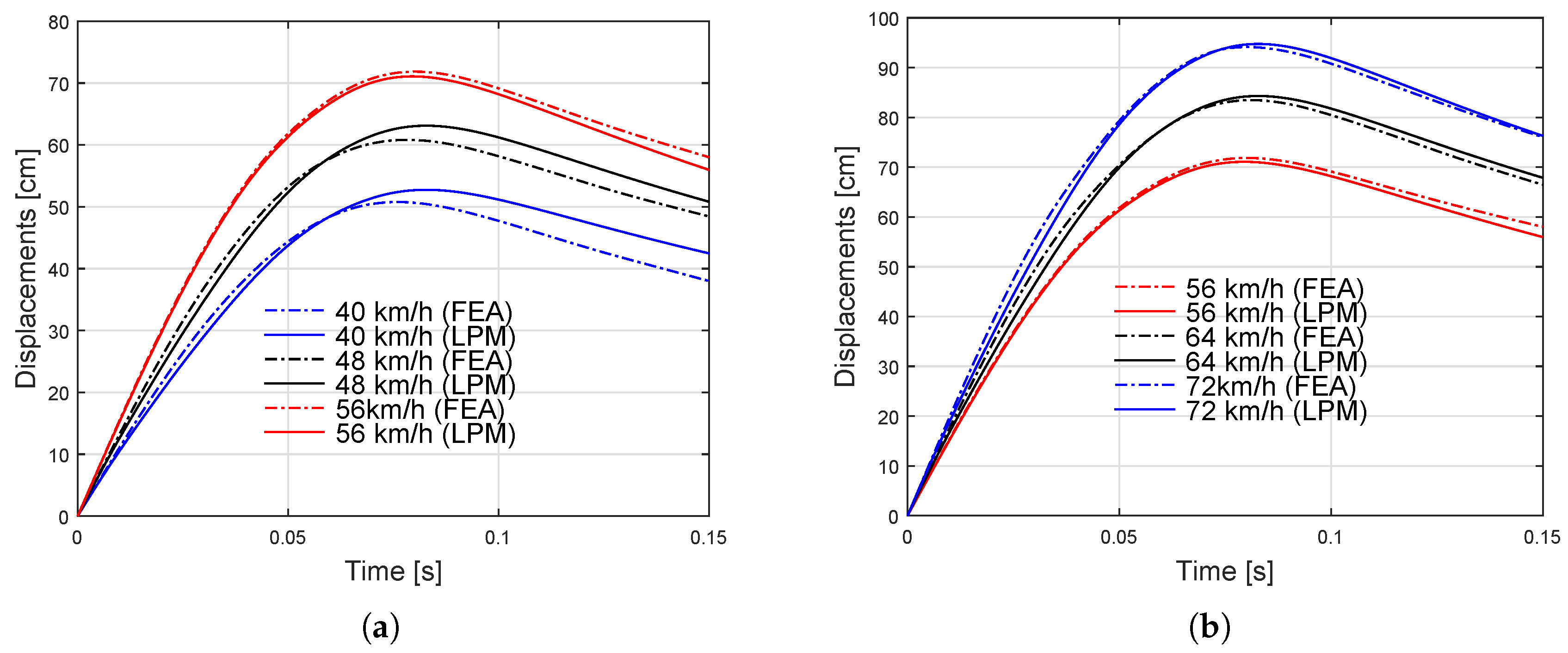
The model developed in this study was validated with reference to a previous study by Munyazikwiye et al34). which utilised a modelling approach of the vehicle structure as a mass–spring–damper system. In that study, a comparison was made between the piecewise lumped parameter model (LPM) and the Finite Element Method (FEM), with results showing that the predictions from the LPM closely matched those of the FEM, both in terms of displacement during frontal collision scenarios, as shown in Figure 6.
In line with this approach, in this study, the dynamic system is also modelled by simplifying the vehicle structure into a mass–spring–damper system and analysed using MATLAB Simulink to evaluate the structural response in terms of displacement, velocity, and acceleration during a frontal collision.
3. Results and Discussion
3.1. Data Analysis
The Dynamic Response Analysis method analyzes the displacement, velocity, and acceleration of the chassis during impact. Then, the simulation results were plotted to visualise the dynamic response. MATLAB Simulink simulation results for the frontal impact scenario are presented as displacement, velocity, and acceleration graphs of the chassis. The dynamic response analysed is for the full-frontal impact chassis35).
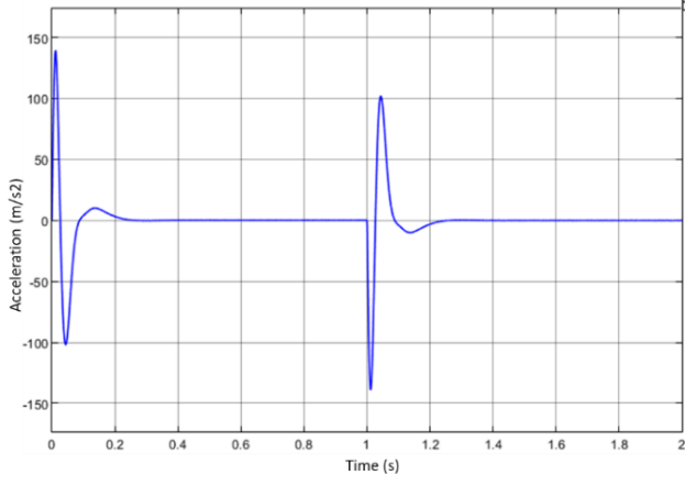
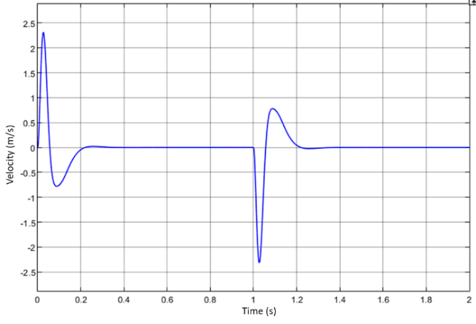
The results of the dynamic response of the full-frontal impact chassis can be presented in the form of three graphs, namely displacement, velocity, and acceleration. tablehe simulation graph shows the displacement response of the chassis structure owing to a frontal collision. Initially, a positive displacement spike of 70 mm in the time range of 0 s to 0.2 s indicates the initial deformation due to the impact. After reaching its peak, the displacement decreases owing to the material's resistance to further deformation. Then, a steady state occurs in the range from 0.2 s to 1 s. Around 1 s to 1.2 s, a negative spike of up to 60 mm occurs, indicating the chassis structure's elastic and plastic recovery effect. This reflects the material rebound or the impact of the energy dispersal mechanism. After 1.2 s to 2 s, the system stabilises again near the displacement value of the chassis structure of 0 mm, indicating that the impact energy has been absorbed by the structural deformation of the chassis. This pattern reflects the characteristics of the deformation zone (crumple zone) and the inertial effect of the chassis mass receiving a sudden external force. This high displacement response can affect the vehicle's performance after impact, including its stability and handling. If the vehicle structure changes significantly, it may affect the reaction of the vehicle to the road after an accident. Figure 8. shows the dynamic velocity response of the chassis structure to impact. An initial spike in velocity to near 2.5 m/s occurs owing to the large impulse force. The velocity then drops dramatically within 0.2 s and undergoes damping oscillations due to energy dissipation in the material. At 1 s, a spike occurs owing to the structure's propagation and reflection of stress waves. The structural response returns to steady around 1.2 s, indicating the damping effect of the chassis structure. The graph in Figure 9. shows the acceleration phenomenon of the chassis structure owing to the impact. At the beginning of the impact at 0 s, the large impulse force caused the acceleration to jump dramatically to 140 m/s², indicating a strong impact on the chassis structure. Immediately afterwards, the acceleration drops sharply to 100 m/s², indicating that the structure undergoes backlash owing to deformation and damping of the impact energy. After the initial phase, the acceleration oscillated with a decreasing amplitude, indicating energy dissipation throughout the chassis. At approximately 1 s, there is a second acceleration spike owing to the reflection of stress waves in the material that propagate and reflect at the boundary of the structure. This was followed by a rapid change in the negative direction, indicating that the structure experienced a backlash against the reflected wave. After several small oscillations, the acceleration finally subsides and approaches zero, indicating that the chassis has fully absorbed the impact energy.
More significant displacement, velocity, and acceleration responses in the impact dynamic model can result in more severe structural damage to the vehicle, increasing the risk of injury to passengers and affecting overall safety. Extreme displacements indicate significant deformations, whereas high velocity increases the kinetic energy at impact, causing greater forces. Meanwhile, high acceleration can result in significant forces being received by passengers, potentially causing serious injuries. Combining these three parameters provides a clear picture of the risks and impacts posed during an impact event.
3.2. Discussion of System Dynamic Response to Impact
The dynamic response of the system shows that the model can capture the main characteristics of the structural behaviour during impact36). This illustrates the importance of the impact position to the system's overall response. The results of this study, compared to previous research using a similar approach in dynamic modelling for crashworthiness, have in common that the model is consistent with previous research regarding displacement, velocity, and acceleration response patterns37). Another similarity is that the steady state achieved aligns with the results reported in the literature however, this study introduces more detailed stiffness and damping variations, which allows a more in-depth analysis of the impact of these parameters on the system response38). This study

utilised the MATLAB Simulink implementation for more complex and accurate simulations.
3.3. Evaluation of Advantages and Disadvantages of the Proposed Model
The model used in this study has several advantages. In terms of accuracy, the model provides an accurate prediction of the dynamic response of the system during impact. From the aspect of parameter detail, this study used more detailed parameters for stiffness and damping, improving the understanding of the influence of each component. From the perspective of the impact scenario, the simulation of the full-front impact scenario provides a comprehensive picture of the system's performance39).
The shortcoming of this study is its complexity. This requires more data and computation time because it uses a more detailed model. In addition, for experimental validation, the simulation results must be validated with experimental data to ensure the model's accuracy under real-world conditions. Thus, this study significantly contributes to vehicle crashworthiness by developing a detailed dynamic model and performing comprehensive simulations using MATLAB Simulink.
4. Conclusions & recommendations
4.1. Conclusions
Based on the findings of this study, the following conclusions were drawn.
•A four-mass dynamic model was successfully developed using MATLAB Simulink to simulate the crashworthiness of the front-end structure of a vehicle. The model captures the dynamic response of the key components of the bumper beam, crash box, and chassis under full-frontal impact conditions.
•Under frontal impact conditions involving an impact force of 72,000 N, an initial velocity of 15.6 m/s (56 km/h), and a duration of 0.2 seconds, the model yielded the following key dynamic responses:
a.The chassis displacement peaked at 70 mm during the initial impact phase, followed by a rebound displacement of 60 mm due to stress wave reflection, before stabilising near 0 mm after 1.2 seconds.
b.The velocity of the chassis reached a maximum of 2.5 m/s, then decreased through damped oscillations, stabilising to near zero within 1.2 seconds.
c.The acceleration reached a peak of 140 m/s² at the onset of the impact, reducing to 100 m/s² during the plastic deformation phase, indicating the effectiveness of the damping and stiffness in force dissipation.
•Although the model provides detailed insights and accurate simulations, its computational complexity requires future experimental validation through physical crash tests to ensure applicability under real-world crash scenarios.
4.2. Recommendations
Future research should focus on validating the simulation results with experimental data to ensure real-world applicability. In addition, integration with other vehicle systems can be achieved by expanding the model to include interactions with the suspension system or other structural components for a thorough analysis.
Material optimisation can be performed by researching advanced materials with superior energy absorption properties to improve crash performance.
For wider applicability in real-world scenarios, it is possible to simulate more complex crash scenarios, such as oblique crashes or multivehicle crashes. Improving the model by incorporating accurate parameters from experiments and recent literature and optimising the MATLAB Simulink simulation process will further improve the quality and accuracy of the model, thus making a significant contribution to the field of vehicle crashworthiness. Considering these aspects, future research can enhance vehicle safety design and contribute to developing innovative solutions in the field of vehicle crashworthiness.
Acknowledgment
This research was supported by a Lembaga Pengelola Dana Pendidikan Indonesia (LPDP) grant from the Ministry of Finance, Republic of Indonesia.
Nomenclature
| Symbol | Description | Unit |
|---|---|---|
| a | Acceleration | m/s² |
| c | Damping coefficient | N.s/m |
| F | Force | N |
| Fa (t) | External impact force function | N |
| I | Moment of inertia | kg·m² |
| k | Stiffness (spring constant) | N/m |
| m | Mass | kg |
| t | Time | s |
| v | Velocity | m/s |
| x | Displacement | m |
Greek Symbols
| Symbol | Description | Unit | |
|---|---|---|---|
| ρ | Material density (if used in context) | kg/m³ | |
| ω | Angular frequency | rad/s |
Subscripts
| Subscript | Description |
|---|---|
| 1 | Refers to bumper beam component |
| 2L | Refers to left crash box component |
| 2R | Refers to right crash box component |
| 3 | Refers to chassis component |
| max | Maximum value |
| ss | Steady state |
References
- K. Sinha, “Reliability-based multiobjective optimization for automotive crashworthiness and occupant safety,” Structural and Multidisciplinary Optimization, 33 (3) 255–268 (2007). doi:10.1007/s00158-006-0050-x.
- Y. Zhang, X. Xu, S. Liu, T. Chen, and Z. Hu, “Crashworthiness design for bi-graded composite circular structures,” Constr. Build. Mater., 168 633–649 (2018). doi:10.1016/j.conbuildmat.2018.02.159.
- M.S. Zahran, P. Xue, M.S. Esa, and M.M. Abdelwahab, “A novel tailor-made technique for enhancing the crashworthiness by multi-stage tubular square tubes,” Thin-Walled Structures, 122 64–82 (2018). doi:10.1016/j.tws.2017.09.031.
- K. Rambhad, V. Sutar, P. Sonwane, and S. Suryawanshi, “A review on automotive bumper beam design and analysis,” Journal of Automotive Engineering &Technology, 5 (1) 21–35 (2020).
- B.A. Behrens, K. Brunotte, H. Wester, and E. Stockburger, “Investigation of the process window for deformation induced ferrite to improve the joinability of press-hardened components,” in: METAL 2020 - 29th International Conference on Metallurgy and Materials, Conference Proceedings, 2020: pp. 579–584. doi:10.37904/metal.2020.3523.
- L. G Keni, V. Singh, N. Singh, A. Thyagi, S. Kalburgi, and K.N. Chethan, “Conceptual design and analysis of a car bumper using finite element method,” Cogent Eng., 8 (1) (2021). doi:10.1080/23311916.2021.1976480.
- Z. Zhang, S. Liu, and Z. Tang, “Design optimization of cross-sectional configuration of rib-reinforced thin-walled beam,” Thin-Walled Structures, 47 (8–9) 868–878 (2009). doi:10.1016/j.tws.2009.02.009.
- M.M. Davoodi, S.M. Sapuan, D. Ahmad, A. Aidy, A. Khalina, and M. Jonoobi, “Concept selection of car bumper beam with developed hybrid bio-composite material,” Mater. Des., 32 (10) 4857–4865 (2011). doi:10.1016/j.matdes.2011.06.011.
- M.S. Han, B.S. Min, and J.U. Cho, “Fracture properties of aluminum foam crash box,” International Journal of Automotive Technology, 15 (6) 945–951 (2014). doi:10.1007/s12239-014-0099-2.
- Q. Gao, X. Zhao, C. Wang, L. Wang, and Z. Ma, “Multi-objective crashworthiness optimization for an auxetic cylindrical structure under axial impact loading,” Mater. Des., 143 120–130 (2018). doi:10.1016/j.matdes.2018.01.063.
- Z. Xiao, J. Fang, G. Sun, and Q. Li, “Crashworthiness design for functionally graded foam-filled bumper beam,” Advances in Engineering Software, 85 81–95 (2015). doi:10.1016/j.advengsoft.2015.03.005.
- I. Kusyairi, “The influence of origami and rectangular crash box variations on mpv bumper with offset frontal test examination toward deformability,” Journal of Energy, Mechanical, Material and Manufacturing Engineering, 2 (2) (2017). doi:10.22219/jemmme.v2i2.5070.
- C. Huang, Y. Hu, S. Zhang, L. Yang, L. Xia, J. Zhang, W. Song, and S. Lo, “A collision-free model on the interaction between pedestrians and cyclists on a shared road,” Journal of Statistical Mechanics: Theory and Experiment, 2021 (10) (2021). doi:10.1088/1742-5468/ac26b4.
- G. Belingardi, A.T. Beyene, E.G. Koricho, and B. Martorana, “Alternative lightweight materials and component manufacturing technologies for vehicle frontal bumper beam,” Compos. Struct., 120 483–495 (2015). doi:10.1016/j.compstruct.2014.10.007.
- Y. Miao, X. Rui, P. Wang, H. Zhu, J. Zhang, and J. Wang, “Nonlinear dynamic modeling and analysis of magnetorheological semi-active suspension for tracked vehicles,” Appl. Math. Model., 125 311–333 (2024). doi:10.1016/j.apm.2023.09.027.
- M.T. AŞKAR, and K. ERMİŞ, “Crash analysis and size optimization of a vehicle’s front bumper system,” International Journal of Automotive Science and Technology, 5 (3) 184–191 (2021). doi:10.30939/ijastech..930944.
- M.S. Ul Abrar, K.F. Nadim Ezaz, M.J. Hasan, R.I. Pranto, T.A. Alvy, and M.Z. Hossain, “Speed-dependent impact analysis on a car bumper structure using various materials,” Results in Engineering, 21 101927 (2024). doi:10.1016/j.rineng.2024.101927.
- S.W. Wang, “Crashworthiness analysis of bumper system based on Ls-dyna,” in: H. Dong, H. Yu (Eds.), Ninth International Conference on Mechanical Engineering, Materials, and Automation Technology (MMEAT 2023), SPIE, 2023: p. 283. doi:10.1117/12.3008231.
- S.K. Vignesh, M. Jaikumar, P. Koenig, and V. Hariram, “Enhancing the crashworthiness of passenger vehicle through modification of bumper beam design and energy absorption materials,” International Journal of Vehicle Structures and Systems, 15 (7) 892–895 (2023). doi:10.4273/ijvss.15.7.04.
- M. Luo, Y. Chen, D. Gao, and L. Wang, “Inversion study of vehicle frontal collision and front bumper collision,” Electronic Research Archive, 31 (2) 776–792 (2023). doi:10.3934/era.2023039.
- N. Nawawithan, P. Kittisakpairach, S. Nithiboonyapun, K. Ruangjirakit, and P. Jongpradist, “Design and performance simulation of hybrid hemp/glass fiber composites for automotive front bumper beams,” Compos. Struct., 335 (2024). doi:10.1016/j.compstruct.2024.118003.
- E.S. Yeshanew, and R.B. Nallamothu, “Numerical simulation and design modification of an automotive bumper to enhance energy absorption by using ls-dyna,” Modelling and Simulation in Engineering, 2025 (1) (2025). doi:10.1155/mse/9980385.
- G.W. Milton, and J.R. Willis, “On modifications of newton’s second law and linear continuum elastodynamics,” Proceedings of the Royal Society A: Mathematical, Physical and Engineering Sciences, 463 (2079) 855–880 (2007). doi:10.1098/rspa.2006.1795.
- M.M. Basit, and S.S. Cheon, “Time-dependent crashworthiness of polyurethane foam,” Mech. Time. Depend. Mater., 23 (2) 207–221 (2019). doi:10.1007/s11043-018-9391-2.
- H.J. Beermann, “Behaviour of passenger cars on impact with underride guards.,” International Journal of Vehicle Design, 5 (1–2) 86–103 (1984).
- Y. Zhang, G. Sun, G. Li, Z. Luo, and Q. Li, “Optimization of foam-filled bitubal structures for crashworthiness criteria,” Mater. Des., 38 99–109 (2012). doi:10.1016/j.matdes.2012.01.028.
- M. Lazarek, P. Brzeski, and P. Perlikowski, “Design and identification of parameters of tuned mass damper with inerter which enables changes of inertance,” Mech. Mach. Theory, 119 161–173 (2018). doi:10.1016/j.mechmachtheory.2017.09.004.
- S. Hou, Q. Li, S. Long, X. Yang, and W. Li, “Multiobjective optimization of multi-cell sections for the crashworthiness design,” Int. J. Impact Eng., 35 (11) 1355–1367 (2008). doi:10.1016/j.ijimpeng.2007.09.003.
- A.A.E. Khattab, “Investigation of an adaptable crash energy management system to enhance vehicle crashworthiness,” Mechanical Engineering, 268 (2011). http://spectrum.library.concordia.ca/7234/.
- M. Gidlewski, L. Prochowski, L. Jemioł, and D. Żardecki, “The process of front-to-side collision of motor vehicles in terms of energy balance,” Nonlinear Dyn., 97 (3) 1877–1893 (2019). doi:10.1007/s11071-018-4688-x.
- B.R. Mitchell, J.C. Klewicki, Y.P. Korkolis, and B.L. Kinsey, “The transient force profile of low-speed droplet impact: measurements and model,” J. Fluid Mech., 867 300–322 (2019). doi:10.1017/jfm.2019.141.
- A. Baroutaji, M. Sajjia, and A.G. Olabi, “On the crashworthiness performance of thin-walled energy absorbers: recent advances and future developments,” Thin-Walled Structures, 118 137–163 (2017). doi:10.1016/j.tws.2017.05.018.
- P. Sathishkumar, J. Jancirani, D. John, and S. Manikandan, “Mathematical modelling and simulation quarter car vehicle suspension,” IOSR Journal of Mechanical and Civil Engineering (IOSR-JMCE), 3 (1) 1280–1283 (2014). www.ijirset.com.
- B. B. Munyazikwiye, D. Vysochinskiy, M. Khadyko, and K. G. Robbersmyr, “Prediction of vehicle crashworthiness parameters using piecewise lumped parameters and finite element models,” Designs (Basel)., 2 (4) 43 (2018). doi:10.3390/designs2040043.
- J. Ma, D. Hou, Y. Chen, and Z. You, “Quasi-static axial crushing of thin-walled tubes with a kite-shape rigid origami pattern: numerical simulation,” Thin-Walled Structures, 100 38–47 (2016). doi:10.1016/j.tws.2015.11.023.
- J. Fang, G. Sun, N. Qiu, N.H. Kim, and Q. Li, “On design optimization for structural crashworthiness and its state of the art,” Structural and Multidisciplinary Optimization, 55 (3) 1091–1119 (2017). doi:10.1007/s00158-016-1579-y.
- Z. Tang, Y. Zhu, Y. Nie, S. Guo, F. Liu, J. Chang, and J. Zhang, “Data-driven train set crash dynamics simulation,” Vehicle System Dynamics, 55 (2) 149–167 (2017). doi:10.1080/00423114.2016.1249377.
- G.P. Cimellaro, “Simultaneous stiffness-damping optimization of structures with respect to acceleration, displacement and base shear,” Eng. Struct., 29 (11) 2853–2870 (2007). doi:10.1016/j.engstruct.2007.01.001.
- G. Li, J. Yang, and C. Simms, “A virtual test system representing the distribution of pedestrian impact configurations for future vehicle front-end optimization,” Traffic Inj. Prev., 17 (5) 515–523 (2016). doi:10.1080/15389588.2015.1120294.