
Abstract
Abstract: Organic Rankine Cycles (ORCs) are widely used for recovering low-temperature waste heat, particularly in renewable energy systems like biomass. However, their performance is often reduced by undetected heat and gas leakage. This review aims to identify, classify, and assess current leakage de-tection methods specifically suited for ORC systems, focusing on their effectiveness under typical operat-ing conditions. The scope encompasses thermal and gas leakage detection techniques, including tempera-ture, pressure, and flow rate monitoring, as well as advanced diagnostic technologies. The main findings indicate that heat loss from components, such as the expander, and undetected vapor leakage can signifi-cantly degrade system efficiency and output. Continuous temperature, pressure, and flow rate monitoring are the most effective methods for ensuring safety and optimizing system performance, among the re-viewed options. Integrating these techniques with Internet of Things (IoT) devices and machine learning offers promising avenues for real-time diagnostics and predictive maintenance. Future research should fo-cus on developing cost-effective, robust sensors suitable for high-temperature and high-humidity envi-ronments common in ORCs. This review contributes to the broader discussion on improving ORC moni-toring and reliability while proposing practical pathways for technological innovation and sustainable en-ergy conversion.
Keywords: heat loss, leakage detection system, Organic Rankine Cycle, system safety, working fluid leakage
Outline
1. Introduction
The Organic Rankine Cycle (ORC), an eco-friendly technology, is an effective alternative for addressing waste heat. More than half of the energy utilized worldwide is lost as heat1). The main waste heat sources include exhaust gases from burners, furnaces, dryers, heaters, and heat exchangers. For a more specific estimate, in the United States alone, the potential for unrecovered waste heat at temperatures below 150 °C is approximately 75 × 10⁹ kW/year2). These findings highlight the substantial potential for ORC deployment in waste heat recovery. Due to the lower boiling points of organic working fluids, ORCs can operate efficiently within this temperature range, converting heat from sources such as exhaust gases, furnaces, dryers, and heat exchangers into electrical power.
Recent studies have shown that the selection of working fluid and operating conditions has a significant influence on ORC performance. It has been shown that matching fluid thermophysical properties with heat source temperatures is essential for maximizing efficiency3), while optimized utilization of exhaust waste heat can significantly enhance net power output and cycle efficiency4). In addition, it has also been reported that incorporating recuperators or additional heat exchangers enables internal heat recovery and leads to superior thermal performance compared to the basic ORC configuration2).
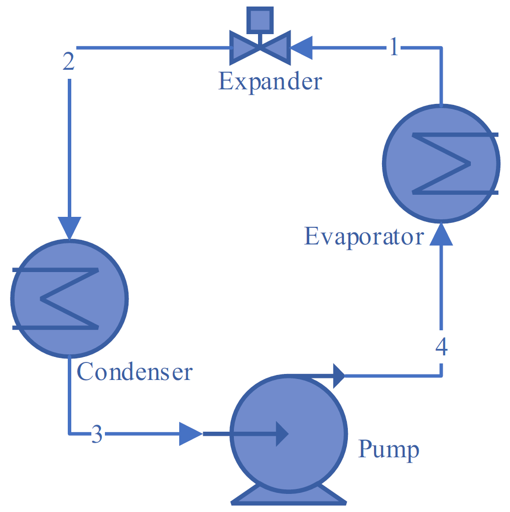
At the system level, a conventional ORC consists of four main components—pump, evaporator, expander, and condenser—undergoing compression, heat addition, expansion, and heat rejection processes, respectively, as illustrated in Figure 11). Rather than serving as background, this schematic provides the reference framework for identifying where heat losses and working fluid leakages are most likely to occur, particularly around the expander and heat exchange components.
Component-level investigations have revealed that heat loss can substantially degrade ORC performance. External heat losses from a small-scale expander, and it was shown that convective, radiative, and conductive losses increase with operating temperature, resulting in a measurable reduction in shaft power5). Structural features, such as the connection between the expander and its support, have been identified as dominant contributors to conductive losses, indicating the need for improved designs and effective heat loss monitoring strategies.
Similarly, working fluid leakage has been shown to affect both safety and thermodynamic performance. The flammability of common ORC working fluids has been identified as an inherent operational risk6). Quantitative risk assessment has demonstrated that ventilation strategies and gas detection devices are critical for safe operation7). From an environmental and health perspective, refrigerant leakage has been shown to contribute to global warming potential, ozone depletion, and human toxicity impacts8). Thermodynamic analyses have further reported that vapor leakage in ORC receivers can reduce net power output by up to 20.81%9), while permeability and internal leakage in micro-ORC systems can cause power losses of several kilowatts and efficiency degradation of up to 4.4%10). Collectively, these studies demonstrate that heat loss and fluid leakage are not marginal effects but critical factors that govern ORC efficiency, safety, and sustainability.
Advances in ORC design and optimization have been synthesized, demonstrating how cycle modifications and component improvements enhance efficiency in ORC applications with solar, biomass, and industrial waste heat sources have been analyzed, highlighting their suitability for diverse energy recovery scenarios11–14). System-level perspectives on ORC power systems and configurations have
been provided15–17), while small-scale and engine waste heat recovery applications have been assessed18–21). Bibliometric analyses have mapped the evolution of ORC research and identified performance optimization and working fluid development as dominant themes22–24). Further reviews have addressed solar ORC development25), working fluid selection and optimization26–29), efficiency enhancement30) and performance evaluation31–33).
Despite these comprehensive contributions, existing reviews predominantly emphasize efficiency improvement through design, fluid selection, and system optimization. To the best of the authors’ knowledge, none has systematically focused on methods for detecting and monitoring heat loss and working fluid/gas leakage in ORC systems. This omission is notable, given that experimental and modeling studies have already demonstrated that external heat losses5) and leakage phenomena9) can cause substantial power and efficiency degradation, while also posing serious safety6) and environmental risks8).
Therefore, a clear research gap exists in the lack of a focused synthesis of leakage detection and monitoring approaches tailored to ORC systems, particularly in relation to operational safety, real-time condition monitoring, and long-term performance reliability. In response to this gap, this review aims to examine and evaluate various heat and gas leakage detection technologies, focusing on their applicability to ORC systems. Although such methods are widely applied in broader thermal and industrial systems, they remain underexplored in the ORC context. By synthesizing recent and impactful studies, this work seeks to clarify current capabilities, identify limitations, and outline future research directions toward safer, more reliable, and higher-performance ORC operation.
This paper is structured as follows: Section 2 outlines the review methodology. Section 3 presents applicable detection methods. Section 4 provides an in-depth discussion. Section 5 evaluates the effectiveness of these methods for ORC systems, and Section 6 outlines future research directions related to system reliability and environmental performance.
2. Method
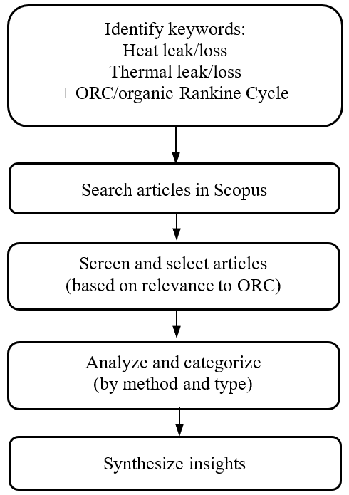
This study employed a narrative semi-systematic review methodology to explore the topic of heat and thermal losses within ORC systems. This approach is especially appropriate for multi-disciplinary research areas and is examined from diverse theoretical and practical perspectives. Unlike a fully systematic review, which requires strict inclusion/exclusion criteria and quantifiable comparisons, the semi-systematic or narrative review allows for a broader exploration of themes and conceptual patterns. Identifying themes, theoretical viewpoints, or recurring issues within a particular research field, or analyzing components of a theoretical concept, are valuable applications of a semi-systematic review34).
The literature search was conducted primarily using the Scopus database, which is known for its comprehensive coverage of peer-reviewed scientific publications. To identify relevant studies, a combination of keywords was used, including ‘heat leak’, ‘heat loss’, ‘thermal leak’, and ‘thermal loss’, each paired with ‘ORC’ or ‘organic Rankine’ to narrow the focus to the specific domain of interest. These keywords were selected to encompass various terminologies commonly used in thermal systems research, ensuring inclusiveness in the search results while maintaining relevance to ORC systems.
After retrieving the relevant articles, the studies were screened and assessed based on their applicability to ORC system configurations. The selected papers were then thematically analyzed and categorized. This categorization enabled the synthesis of key insights, including advantages and disadvantages, emerging trends, and potential directions for future ORC research. The flow of the review process is depicted in Figure 2.
3. Available Leakage Detection Methods
Based on insights from various articles, the broad principles applicable to heat and gas leakage detection in ORC systems can be categorized alphabetically as follows: (1) energy balance calculations, (2) flow rate measurement, (3) heat transfer analysis, (4) optical analysis, (5) pressure monitoring, (6) temperature monitoring, (7) ultrasonic leakage detection, and (8) vibration/acoustic analysis. Among these methods, (1) and (3) rely on calculations or simulations, making them well-suited for detecting heat loss. In contrast, the remaining methods involve physical measurements and are more appropriate for monitoring working fluid leakage. Notably, temperature monitoring using infrared (IR) thermography can be applied to detect heat loss and fluid leakage.
3.1. Energy balance calculations
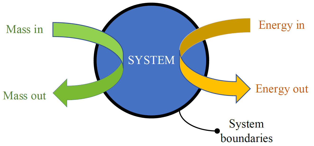
Energy balance calculation is a method to measure energy transfer in a system, by taking into account energy gain and loss35). Energy balance involves calculating all forms of energy, including thermal, mechanical, chemical, and electrical energy, which are input, output, or transformation in a system36). This method is widely used to assess system efficiency and identify energy loss, for example, due to system leakage36–38). The application of this method is demonstrated, among other things, by Saini et al38) to calculate the efficiency and heat rate of the Unit 2 PLTU Takalar (Punagaya) system and Elhanafi et al.37) to evaluate the performance of the Oscillating Water Column (OWC). In general, energy balance involves mathematical equations that show the interaction between energy entering and energy leaving a system based on units of operating time39). The general diagram of energy balance is shown in Figure 3.
This method is based on the conservation of energy, as formulated by Smith et al.35), where the energy input equals the energy output plus the change in system energy. Elhanafi et al.37) demonstrated that deviations in this balance can be used to quantify unaccounted losses, while Bernardi et al.40) showed that detailed energy balance terms enable the identification of hidden inefficiencies. Karim et al.41) further reported that persistent energy imbalance is a strong indicator of system leakage. For ORC applications,
Mahmoudi et al.42) derived a simplified energy balance formulation and showed that deviations from the expected balance directly reflect heat loss or working fluid leakage.
The organic Rankine cycle (ORC) is similar to the steam Rankine cycle (SRC), except that the water in the SRC is replaced by organic compounds (e.g., hydrocarbons, refrigerants, ethers, and siloxanes), while the other components are the same, namely the vaporizer, expansion device, condenser, and pump43). Energy balance, as part of the ORC thermodynamic analysis, involves calculating the energy entering, leaving, and transforming within each component of the ORC44). The purpose of this analysis is to ensure the conservation of energy according to the first law of thermodynamics, namely that the energy entering the system must be equal to the energy leaving and transforming within the system44). If the energy entering the system and the energy leaving the system have a significant difference, which the system’s efficiency cannot explain, then this indicates a leak. The application of the energy balance equation to evaluate ORC was carried out by Carcasci et al.45).
The advantages of this method are that it helps optimize processes, reduce energy waste, and improve overall efficiency by identifying and correcting areas of energy loss36). Energy balance calculations provide insight for improving system design37). However, energy balance calculations require a significant amount of resources to accurately measure all energy inputs and outputs.
3.2. Flow rate measurement
Flow rate is measured by mass flow meters, which measure the mass of a fluid moving through a device over time. Since volumetric flow rate depends on thermodynamic parameters such as temperature and pressure, mass flow rate measurement is a useful flow metering method for industrial metrology. This is because mass flow rate is independent of changes in viscosity, density, temperature, and pressure46). Three mass flow measurement methods are direct, indirect, and thermal. The direct technique measures momentum, Coriolis force, and other characteristics directly related to mass flow. The indirect technique combines a volumetric flowmeter and a densitometer, and correlations are used to infer mass flow. The indirect approach is rarely used in real applications. Meanwhile, the thermal method analyzes thermal conductivity and specific heat, which can be connected to mass flow by heat transfer or heat dissipation via heating/cooling fluid. The devices comprise a thermal profile flow meter, a Thomas flow meter, a boundary layer-type mass flow meter, and a hot-wire anemometer that measures heat dissipation46). For an ORC system, Coriolis mass flow meters are generally more suitable due to their accuracy, versatility, and durability in handling the specific requirements of ORC operations47). The practical relevance of Coriolis mass flow meters has been demonstrated in several ORC studies. Their use has enabled the identification of pressure pulsation and cavitation phenomena in micro-ORC systems, as well as the accurate quantification of cycle performance and efficiency in low-grade heat recovery applications48–51). More recently, high-resolution mass flow measurements are essential for characterizing variable-speed ORC operation and capturing transient performance behavior48–51).
Monitoring the mass flow rate of the working fluid is essential in ORC. Another study showed that mass flow rate is a key parameter to be controlled in a plethora of ORC studies52). It is common to analyze the effects of the working fluid’s mass flow rate on key parameters, such as the expander’s inlet-outlet pressure and temperature, the shaft’s rotational speed, and power53). The effect of varying mass flow rates and heat source temperatures on a steady-state operation characteristic of an ORC using R123 and a scroll expander showed that the isentropic efficiency of the expander sharply increases with mass flow rate, even though it decreases slightly initially54). It is suggested that optimizing the mass flow rates of the heat source, working fluid, and cooling water is part of the operation optimization problems of an ORC; setting them in a suitable allocation value could yield the highest net power production or efficiency55).
Not only for performance, controlling ORC systems is critical to their safety52). Thus, measuring, monitoring, and controlling the mass flow rate are also included in maintaining the safety of an ORC. A research study investigated a control method to prevent working fluid from entering the ORC-based system’s expander as moist vapor56). They propose two approaches to ensuring safe transient operation: managing the mass flow rate of the cooling water at the condenser or controlling the mass flow rate of the working fluid.
Leakages within an expander can significantly impact both the expander’s properties and the cycle conditions. It is related to the mass flow rate in Eq. 1, which represents the evaporator’s energy balance. When the working fluid enters the evaporator with constant heat input and enthalpy, the output enthalpy of the vapor is proportional to its mass flow. Furthermore, vapor pressure entering the expander depends on its mass flow rate. Assuming steady-periodic conditions, the total mass flow rate through the expander can be calculated as the sum of the theoretically displaced mass flow rate and the mass flow rate through the leakage, as expressed in Eq. 257).
Where M is mass flow rate (kg/s), h is specific enthalpy (J/kg), and Q is heat flux (W).
The permeability effect in ORC can also be detected using the mass flow rate. ‘Permeability’ is the relationship between mass flow rate and maximum pressure of an ORC that shows the plant’s ability to traverse the working fluid. The higher the volumetric losses, the greater the mass flow rate circulating inside the plant at a given maximum pressure10).
Mass flow rate measurement in ORC can support two purposes. It is a key parameter in supporting performance optimization and leakage detection in ORC. Moreover, mass flow rate can also be used to detect leakage from the permeability of the ORC system.
3.3. Heat transfer analysis
Heat transfer is a scientific field that studies how heat is transferred between objects through various media58). This transfer occurs due to temperature differences58). The ORC is a technology used to generate electrical energy from low- to medium-temperature heat sources9). In the ORC cycle, thermal efficiency highly depends on heat transfer across its components59). Thermal efficiency is the ratio of the energy converted into net power to the total energy available from the heat source60) and it reflects how effectively a system uses available energy to generate power60).
Understanding heat transfer is essential for assessing how heat moves from the source to the working fluid in each ORC loop, which impacts the system’s energy generation efficiency60). One key parameter influencing thermal efficiency is the heat transfer coefficient, which indicates how effectively heat is transferred between the working fluid and the heat exchanger in the ORC59). The heat transfer rate in each zone is calculated using the energy balance principle, ensuring that the amount of heat received or released by the fluid matches the energy transferred throughout the system61). When the overall heat transfer coefficient is optimized, heat transfer between the working fluid and the heat exchanger occurs efficiently59).
The heat transfer coefficient in an ORC system is typically calculated using theoretical and empirical correlations59,61). These correlations help determine the heat transfer efficiency between the flue gas and the working fluid under various operating conditions61). Calculating the heat transfer coefficient is crucial for designing an efficient ORC, as it ensures maximum utilization of waste heat energy60). Moreover, heat transfer analysis can also detect leakage in the ORC system, as leakage can disrupt flow patterns and create uneven temperature distributions62,63). Leakage can affect pressure, temperature, and fluid flow in the system, and can be identified by comparing thermodynamic parameters before and after the leakage9). Abnormal changes in these parameters suggest the presence of a leak. Monitoring heat transfer characteristics, such as temperature and fluid pressure, can also help detect leakage. Anomalies, such as unusual temperature fluctuations or sudden changes, indicate leakage in the system. Integrating temperature sensors into key components can aid in the real-time detection of these abnormalities.
The advantages of using heat transfer analysis for leakage detection include real-time detection, high accuracy in measuring leakage through the heat transfer coefficient, and identification of energy losses that may not be detectable otherwise. However, a key challenge lies in identifying the correct correlations to predict thermal performance accurately59). Successfully modelling heat transfer and comparing it with observed data can serve as an important tool for early leakage detection in ORC systems59).
3.4. Optical analysis
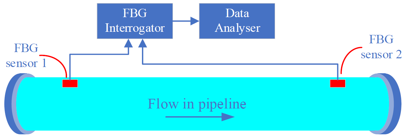
Fiber Bragg Grating (FBG) is a distributed Bragg reflector constructed from short optical fiber sections. It allows the passage of various light wavelengths while reflecting specific ones. The reflection occurs due to periodic alterations in the refractive index of the fiber core, typically induced by a strong ultraviolet light interference pattern. In an FBG sensor, the Bragg grating functions as a wavelength-selective mirror when illuminated by a broadband light source, reflecting certain wavelengths in response to variations in strain or temperature. This property allows FBG sensors to monitor variations in different physical parameters such as strain, temperature, pressure, and vibration, among others64). In practice, these sensors can identify damage such as circumferential cracks and delamination, locate impacts, or detect and monitor leakage65). Figure 4 shows the basic principal of measuremen using FBG.
Pipeline leakage detection experiments using an FBG pressure transducer are conducted using a galvanized steel pipe on a laboratory scale equipped with 5 pairs of valves66). Two different sizes of artificial leakage are inserted into the pipe to measure the application of the FBG sensor in detecting leakage. The FBG sensor is mounted on a pressure transducer connected to the pipe during the experimental work. The findings indicate that larger leakage sizes result in higher stress drops in the pipe. This study shows that FBG is a reliable method for leakage detection, as it is highly sensitive to pressure changes in the pipe and shows good uniformity.
The application of FBG sensors to detect natural gas pipeline leakage is studied in the paper67), among others. FBG strain sensors are wrapped around the pipe wall. Pressure changes inside the pipe cause the pipe to expand or contract, with the annular strain of the pipe changing accordingly. FBG strain sensors detect pressure changes inside the pipe by sensing the annular strain. Meanwhile, an FBG gas leakage detection sensor has been designed in68) which
utilizes the energy provided by beam propagation in optical fiber to avoid external temperature interference effectively. This sensor can not only provide real-time monitoring of leak-prone pipe sections, but also provide quantitative data on fluid leakage velocity. In another application, the FBG sensor monitors and detects hydrogen leakage69). This sensor is presented using the classic Pd (palladium) coating technique as the hydrogen-sensitive film to enhance the detection of hydrogen molecules and precisely increase the absorption of hydrogen molecules.
also been applied to water leakage monitoring in different engineering systems. An FBG-based measurement system has been developed to address practical requirements and limitations, demonstrating that pressure, flow rate, and vibration measurements can be integrated to improve the sensitivity of water leakage detection70). Simulation and experimental studies have further shown that distributed FBG sensing can identify leakage-prone zones in high-temperature industrial environments, such as the burner area of electric arc furnaces71), as well as in large hydraulic structures, including concrete face rockfill dams, where localized temperature disturbances indicate seepage paths50).
FBG sensors are also used to detect the potential leakages in the diaphragm wall joints, which are commonly used in deep underground construction projects72). The temperature field of the detection tube is artificially elevated to a preset value using an electric heating belt. The preset value is determined depending on the surrounding temperature. The temperature field of the detection tube is then simultaneously monitored using the FBG sensor, from the top to the bottom of the tube. If a leakage occurs, the temperature of the detection tube at that point decreases because the leaking water absorbs some of the thermal energy from the pipe at that location. Thus, the signal captured by the FBG sensor can be processed to determine whether there is a water leakage.
The use of FBG sensors for monitoring the technical condition of a 3 kW ORC microturbine has been described in Mieloszyk et al. and Jurek et al.65,73). The sensors were used to determine temperature distribution and detect a leakage of a low-boiling medium. It was found that FBG sensors can effectively measure temperature changes on the turbogenerator casing and monitor the condition of the connections between the components of the turbogenerator casing for leakage detection.
FBG is often used as a sensor in structural health monitoring (SHM) systems due to its advantages, including high sensitivity, high accuracy, intrinsic safety, multiplexing capabilities similar to wavelength division multiplexing (WDM), immunity to electrical and magnetic interference, and optical communications with optical sensing.
The other advantages of Fiber Bragg Gratings (FBG) include simple sensor installation, lower cost, and insensitivity to interference signals. Additionally, FBG exhibits small attenuation along its path, is sensitive to small leakage and low noise, and features a compact size and lightweight design. It also offers high corrosion and temperature resistance, does not require calibration, and operates without the need for an electric current in the measurement array65,67). However, the FBGs-based sensor incurs the problem of the grating decay and instability with time, especially when the FBG operates continuously under pressure and at high temperatures69).
3.5. Pressure monitoring
Pressure monitoring has been widely applied for detecting leaks across various engineering systems. In pipeline and water distribution networks, pressure transient analysis and pressure decay techniques have been shown to effectively detect leakage events and support fault localization under operational conditions, particularly when supported by advanced pressure monitoring approaches74,75,76), as well as by broader insights from comprehensive leak detection reviews77-79). These capabilities are further strengthened through pressure‑wave based leak analysis80,81) and complementary understanding of system‑level fluid and energy performance82) 74–82). For storage applications, time-series analysis of pressure data has demonstrated the capability to identify early-stage leaks in tanks by capturing subtle pressure trends83,84). In industrial processes, continuous pressure sensing combined with operational data analysis has enabled non-invasive, real-time leakage detection in complex systems85). Furthermore, statistical comparisons between current and historical pressure measurements have been reported to improve detection sensitivity and reduce false alarms in practical implementations80,86).
Pressure monitoring for leakage detection works by continuously tracking the pressure within a pipe or system to identify discrepancies that may indicate a leakage87). Sensors are installed at various points along the pipeline, and the pressure readings are measured against expected values based on the system’s normal operating conditions. If there is a sudden drop or sustained reduction in pressure, it suggests that fluid is escaping due to a leak. The system can then trigger an alarm or alert operators to pinpoint the leak’s location, allowing for timely maintenance and repair.
The differential pressure method is a better method for detecting small leakage rates. The differential pressure method’s airtightness detection technique primarily compares the air pressures in the tested and master cavities using a certain construction. The tested body is in a good airtight state if the air pressures in the master cavity and the tested cavity are equal. The tested cavity has leaked if there is a pressure differential between it and the master cavity. Figure 5 displays a structural representation of the differential-pressure detection technique88).
The ORC is a thermodynamic cycle that converts heat into mechanical energy, similar to the traditional steam Rankine cycle, but using an organic fluid (working fluid)

instead of water89). An evaporator, an expander, a condenser, and a pump are the four primary parts of a basic ORC2). Experimental and modeling studies have shown that pressure monitoring at key locations in the cycle enables the assessment of component performance during evaporation, expansion, condensation, and compression, and provides an early indication of leakage and operational anomalies90–92).
Pressure monitoring techniques for leakage detection in ORC systems utilize pressure sensors and transducers strategically placed at key locations, such as the evaporator, condenser, and working fluid lines. These sensors track real-time pressure changes within the system. A significant drop in pressure or deviations from normal operating levels can indicate the presence of a leak. In some cases, differential pressure measurements between two points can help pinpoint the location of the leak. By continuously monitoring pressure and comparing it to expected levels, leakage can be detected early, saving further damage, resource loss, or safety issues.
Using pressure monitoring for leakage detection in ORC systems offers several advantages, including the early detection of refrigerant leaks, which helps prevent performance degradation and system failure. Pressure sensors can detect abnormal pressure drops, indicating leakage, allowing for timely maintenance and reducing operational costs. This method is cost-effective, as it avoids the need for more complex and expensive leakage detection technologies. Additionally, continuous pressure monitoring enhances system reliability and safety, ensures optimal efficiency by maintaining proper pressure levels, and reduces environmental impact by minimizing refrigerant loss.
However, it presents several challenges, including the difficulty in distinguishing between pressure changes caused by leakage and those resulting from normal system fluctuations, such as temperature variations or load changes. Accurate pressure measurement requires high-quality sensors, which can be costly and prone to calibration issues. Additionally, pressure sensors may not detect small or slow leakage, especially in systems with complex configurations or low-pressure environments. Environmental factors, such as vibration or extreme temperature fluctuation, can also affect sensor accuracy, potentially leading to false alarms or missed leakage.
3.6. Temperature monitoring
Real-time temperature monitoring using thermocouples, thermistors, RTDs, etc., plays a critical role in maintaining both the performance and safety of an ORC system. Temperature fluctuations can significantly impact the efficiency of heat transfer and the stability of the working fluid, potentially resulting in reduced power output or even component failure. Continuous monitoring enables operators to detect abnormal conditions such as overheating, thermal imbalances, or unexpected thermal losses, allowing for immediate response. Meanwhile, another method for temperature monitoring, such as IR thermography, can be added periodically to enhance safety because this method can detect real-time leakage.
Infrared thermography is a technique that captures infrared radiation emitted from objects within the wavelength range of 700 𝑛𝑚 to 1 𝑚𝑚. It is widely used for applications such as detecting gas and liquid leakage. The core principle behind this technology is the Stefan-Boltzmann law, which relates the infrared radiation emitted by an object (E) to its temperature (T) via the equation 𝐸 = 𝜎𝑇⁴, where σ is the Stefan-Boltzmann constant. While infrared thermometers utilize this principle for precise point measurements, thermal imaging cameras offer a broader capability by providing a visual representation of temperature distributions across a larger area (see Figure 6). Therefore, the choice between infrared thermometers and thermal imaging cameras depends on the application and the level of detail needed.
Infrared thermography is particularly effective for detecting leakage, as leakage often causes temperature differences visible in thermal images. If the leaking substance has a temperature that differs from its surroundings, the temperature variation becomes evident in the infrared spectrum. This makes thermal imaging cameras highly effective for both gas and liquid leakage detection. Studies on water pipeline systems have demonstrated that thermal imaging can identify liquid leakage through surface temperature disturbances and enable rapid localization of fault points, particularly when supported by thermographic reliability assessments for buried pipelines93,94) 93–99). Large‑scale implementations have further shown the benefits of airborne thermal monitoring of district heating networks95,96), while field‑deployable solutions have leveraged thermal‑imaging‑based wireless sensing97). In gas distribution networks, infrared cameras have been reported to detect leakage plumes and quantify gas release based on thermal contrast with the surroundings98,99) 93–99) To improve detection accuracy, recent works have shown that image enhancement and machine learning–based analysis of thermal images significantly improve sensitivity and reduce false detections under complex operating conditions, particularly through infrared‑based gas leakage imaging100, 101), supported by thermographic autofocus for leak localization102), and further strengthened by AI‑driven thermal leak recognition103,104,105). 97,99–105).
Thermal monitoring methods, including the use of thermal
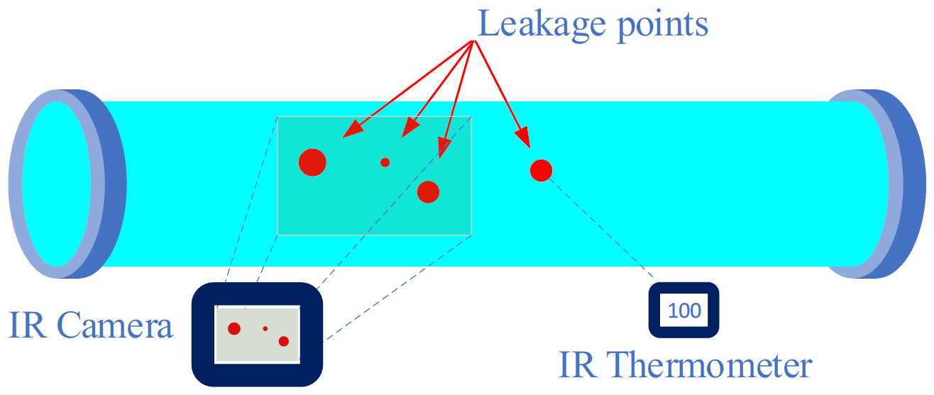
infrared sensors and imaging cameras, can also effectively detect gas leakage by identifying thermal anomalies. Experimental and field studies have shown that temperature drops caused by gas expansion can be captured by thermal imaging and used to localize leakage points in pressurized systems, 106–110). Continuous temperature profiling has further been demonstrated to reveal abnormal surface temperature fluctuations associated with gas leakage under operational conditions, enabling early fault detection and real-time monitoring 87–97).
Infrared thermography offers several advantages when applied to ORC systems. It is a non-contact, non-destructive technique that facilitates real-time, wireless monitoring. This enhances operator safety by enabling remote detection of leakage and issues. It is also a cost-effective solution for continuous monitoring. However, certain challenges remain, such as limited resolution for detecting smaller leakage, the influence of surface material, distance, and interference from environmental factors, which are similarly highlighted in broader evaluations of pipeline monitoring technologies106,107).
Thermal monitoring is especially valuable in ORC systems for a number of reasons. First, safety is a key concern, as ORC systems often involve the use of organic fluids that can be hazardous or flammable7,111). Early leakage detection is critical in preventing accidents. Studies on ORC heat exchangers have demonstrated that gas leakage disrupts local temperature gradients, producing thermal anomalies that can be captured by infrared monitoring, a behavior consistent with sensor‑fusion‑based gas leak localization108,109) and UAV‑assisted thermal detection strategies110) 106–110). Thermal imaging can also help identify cooling effects in the condenser sections of the system, which may signal a gas leak. Additionally, continuous thermal monitoring contributes to improved efficiency by detecting heat losses or leakage in the system. Advanced thermal monitoring can be integrated with the ORC control systems, using machine learning algorithms to provide real-time alerts, enabling prompt responses to potential issues.
Infrared thermography has been reported to offer several practical advantages for leakage detection in ORC systems. Non-invasive thermal inspection has been shown to reduce ignition risks when monitoring flammable working fluids 112,113). Real-time thermal imaging has enabled rapid identification of leakage events and shortened response times under operational conditions114–116). Wide-area thermal scanning has further been demonstrated to be suitable for large-scale ORC facilities, allowing simultaneous monitoring of multiple components108,117). High thermal sensitivity has been reported to support early detection of small temperature anomalies associated with incipient leakage118,119). In addition, integration of thermal monitoring with automated control and alarm systems has been shown to enhance operational efficiency and safety120). The visualization of thermal fields has also been demonstrated to facilitate rapid interpretation of anomalies and assist operators in locating leakage points during inspections, as highlighted in comprehensive leak‑detection reviews121,122), supported by fiber‑optic sensing developments for pipeline diagnostics123), and further strengthened through AI‑enhanced infrared leak interpretation124,125) 120–125).
Despite these advantages, certain disadvantages should also be considered. Field studies have shown that environmental conditions, such as wind, rain, and fluctuating ambient temperatures, can distort thermal signatures and reduce detection accuracy under outdoor operation113,126). It has further been reported that leakage of gases producing weak thermal contrast, or occurring in regions with limited heat dissipation, may remain undetected by infrared imaging112,117,127). Economic assessments have indicated that the high initial cost of thermal imaging systems can constrain large-scale deployment128,129). In addition, thermal anomalies unrelated to leakage have been shown to generate false alarms, requiring careful discrimination during analysis120,123,130–132). Accurate interpretation of thermal data has also been reported to depend on operator expertise, increasing operational complexity123,133), while regular calibration and maintenance are necessary to ensure long-term accuracy and reliability of the equipment111,123).
In conclusion, while infrared thermography offers significant benefits for leakage detection and system monitoring in ORC plants, its effectiveness depends on careful implementation, consideration of environmental factors, and addressing its limitations. As technology advances, infrared thermography is expected to become even more reliable and efficient, making it an increasingly valuable tool for maintaining the safety and performance of ORC systems.
3.7. Ultrasonic leakage detection
Ultrasonic leakage detection (ULD) is a non-destructive and non-invasive method used to detect leakage in pressurized systems. This method utilizes sound waves at high frequencies, typically above 20 kHz134–137). When pressurized gas or liquid escapes through a small gap (see Figure 7), the resulting turbulence generates ultrasonic waves that are inaudible to humans but can be detected by specialized sensors138). These sensors convert the ultrasonic waves into electrical signals, which are then processed to determine the presence and location of leakage139,140).

This technology enables leakage detection without direct contact and without damaging the system, making it highly suitable for real-time monitoring in high-risk industries135,141).
ULD has been applied to various systems and processes, one of which is detecting gas leakage, such as SF6, in electrical power systems142). SF6 is an insulating gas used in electrical equipment, and its leakage can reduce insulation efficiency and pose environmental risks142). Additionally, ULD is utilized in nuclear reactor cooling systems, where ultrasonic sensors detect leakage through guide tubes installed around cooling pipes141).
The use of ULD is not limited to these applications, but also includes detecting pipeline leakage135), refrigerant gas leakage (R290) in refrigeration equipment, air conditioners, and heat pumps (RACHP)134). Moreover, ULD is employed to detect leakage in various components such as wellheads, tubing, tubing connections, gas lift mandrels, packers, and production casings139), as well as fuel tanks143) and pressure vessels144).
There are two main detection principle approaches in ULD: passive ultrasonic leakage detection and active ultrasonic leakage detection144). The passive method operates by sending ultrasonic waves into the tested system without altering the internal pressure. These ultrasonic waves propagate through leakage paths and are captured by external sensors that move around the system. This approach is highly effective when increasing the system pressure is not feasible or may heighten the risk of dangerous leakage144).
On the other hand, the active leakage detection method uses high-frequency sound waves generated by turbulence when pressurized fluid leaks through a small gap144). This leakage creates a turbulent flow that emits sound at ultrasonic frequencies, typically between 30 and 50 kHz, which is then detected by ultrasonic sensors. In this method, the sound frequency produced is closely related to the size of the leakage gap and the fluid flow velocity; the smaller the leakage gap, the higher the sound frequency. However, a limitation of this method is that it can only be applied to pressurized systems and is less suitable for toxic or explosive gases, as increasing the pressure may pose additional risks. Since ORC is a pressurized system, the active leakage detection method can be used.
Ultrasonic leakage detection offers numerous advantages in maintaining the efficiency and safety of ORC systems. It enables the detection of small leakages that are difficult to identify using conventional methods, ensuring ORC efficiency is preserved. Early leakage detection enhances safety, prevents energy efficiency loss, and reduces repair and replacement costs for working fluids. The technology allows for leakage inspections without halting operations, minimizing downtime, and provides fast and accurate detection to enable prompt responses to issues. It is effective in detecting leakage of various organic fluids, such as hydrocarbons and refrigerants, and helps identify leakage with potential environmental impacts, such as refrigerant releases. By detecting problems early, ultrasonic methods support predictive maintenance, preventing damage and reducing risks like fire and explosions from flammable working fluids. Additionally, the system is capable of detecting leakage in complex components and connections within ORC systems, including those involving high-pressure fluids and high-velocity flows that generate detectable ultrasonic signals. Real-time monitoring enables continuous leakage detection, facilitating immediate corrective actions, ensuring ORC systems comply with safety and environmental regulations.
Implementing ultrasonic leakage detection (ULD) in ORC systems presents several challenges due to the unique characteristics of organic fluids and system conditions. The acoustic properties of organic fluids differ significantly from air, requiring calibration and customization of ultrasonic tools to account for fluid-specific behaviors and physical properties. High temperatures, mechanical vibrations, and low pressure in ORC systems can impact detection accuracy. At the same time, insulation on pipes and the placement of sensors on critical components can reduce ultrasonic signal strength. Additionally, background noise, external interference, and low-pressure leakage contribute to false alarms and decreased sensitivity, especially as the detection range increases. The effectiveness of ULD is also influenced by the size of the leak, pressure levels, and the need to adjust for high-temperature conditions common in ORC systems. Customizing the sound field for specific components and optimizing signal frequencies are essential to mitigate signal distortion and enhance detection accuracy. Environmental factors, such as weather, further affect performance, emphasizing the importance of system-specific adaptations for reliable leakage detection.
3.8. Vibration analysis
The vibration analysis method is an approach that examines vibrations in machinery systems145,146). Vibration itself can be defined as a movement from a reference position caused by a force. Vibration analysis (VA) is widely implemented in industries and has proven effective for early failure detection147). Vibrations are measured by transducers, with commonly used types including accelerometers, ultrasound sensors, and tachometers. These transducers transmit signals to the system146) as oscillatory

movements, which are then analyzed for their wave characteristics. Techniques such as the Fourier transform, cross-correlation, and spectral density analysis are often used to analyze and detect characteristics of leakage or damage caused by vibration145,147,148). Figure 8 represents the basic principles of measurement using VA.
The waves generated will vary depending on the machine used and its operation. When the machine is in a healthy and normal condition, it will form a specific pattern that serves as reference data for detecting abnormalities. The variables required for the analysis process are amplitude, frequency, and spectrum147). Waves above normal levels can lead to faster wear or machine failure, making VA an important tool for monitoring machine health and identifying damage or potential failures.
VA has been applied in various sectors. Its effectiveness has been demonstrated in transportation systems and drilling operations, where vibration signatures were used to identify abnormal flow-induced disturbances147,148). In power generation and aviation applications, VA has been reported to support early fault diagnosis in piping networks and rotating machinery under operational conditions147,150). In piping systems, VA has been shown to enable leakage detection and localization by capturing vibration patterns induced by escaping fluids145,147,148,151,152). Beyond localization, experimental studies have further demonstrated that vibration features can be correlated with leakage rates147) and used to assess the severity of damage in mechanical components such as bearings and gearboxes150,153).
Although applications of VA in ORC systems remain limited, these reported capabilities indicate its potential for ORC condition monitoring. Given that ORC plants rely on extensive piping networks to transport organic working fluids, VA could be employed as a predictive maintenance tool to identify incipient leakage and mechanical degradation. This is particularly relevant because commonly used ORC working fluids, such as n-pentane, are highly flammable, making early fault detection essential for safe operation154).
Inexpensive equipment, easy installation and setup, along with high accuracy in detecting damage153,155), making vibration analysis (VA) a popular method for monitoring machine health. The accuracy of VA can exceed 82%145,155). However, VA also has limitations, particularly when analyzing normal conditions, as it often overlooks transitional states such as changes in speed147). This weakness can be addressed by using real-time data obtained through time-series analysis or snapshot measurement147).
4. Discussion
Leakage and heat loss detection methods in ORC systems can be categorized into two primary categories: field measurements and calculation—based methods, also known as simulation-based methods. Field measurement techniques dominate current practice and can be classified further based on their function, either for performance monitoring or safety monitoring.
Performance-monitoring methods, such as flow rate and pressure sensors, are typically embedded into the ORC system to enable real-time data collection, supporting both leakage detection and operational optimization. In contrast, safety-only methods, such as ultrasonic leakage detection (ULD), infrared thermography, and optical analysis, are generally deployed intermittently during scheduled inspections or fault diagnostics.
Calculation- or simulation-based techniques, such as energy balance and heat transfer analysis, are less frequently used but offer crucial advantages. These methods enable system-wide predictions of potential thermal losses and inefficiencies, allowing for proactive mitigation strategies during both the design and operational phases. They depend heavily on real-time data inputs—flow rate, pressure, and temperature—highlighting the dual utility of field sensors for both real-time diagnostics and simulation validation.
This dual categorization is depicted in Figure 9, which classifies the monitoring methods based on real-time capability and application purpose (performance or safety). Techniques such as flow rate and pressure monitoring play central roles due to their high relevance to both objectives, while methods like infrared thermography and optical imaging are primarily focused on safety and are not continuously embedded.
Further comparative analysis, using Figure 10—a radar chart of six performance criteria: accuracy, cost, real-time capability, sensitivity, maintenance, and robustness—highlights trade-offs across methods. Notably, Fiber Bragg Grating (FBG) sensors, originally developed for structural health monitoring156), demonstrate excellent performance across most metrics, and are increasingly favored for long-term integration in ORC systems 65,73) due to their cost-effectiveness157). In contrast, optical analysis offers high sensitivity and accuracy but suffers from high cost and complexity, limiting its practical adoption in smaller-scale ORC applications.
The summary table analysis, as shown in Table 1, further emphasizes these patterns. Key observations include:
•Flow rate and pressure monitoring consistently rank high in cost-effectiveness, reliability, and ease of integration, making them staples in both small- and large-scale ORC deployments.
•Vibration and acoustic analysis, although not as accurate as thermal or flow sensors, offer valuable insights in low-cost setups or where mechanical degradation is a primary concern.
•Energy balance calculations, while indirect, enable systemic efficiency analysis and help infer leakage when direct measurement is impractical.
•Optical and thermal imaging methods provide localized, high-resolution insights, but they sacrifice portability and real-time capability.
•ULD and FBG sensors score favorably across multiple metrics, especially in modern, compact ORC designs emphasizing continuous safety monitoring.
An important emerging trend is the integration of hermetically sealed ORC systems, particularly in units operating around 130°C158,159). These systems, featuring integrated expanders and generators, significantly reduce the risk of leakage. For these systems, indirect methods—such as flow deviation tracking or pressure decay tests—become more critical for long-term monitoring.
This evolution in system design is reflected in Figure 11, which outlines the transition from isolated sensors toward AI-driven, integrated monitoring frameworks. The direction of innovation is clear: the future lies in combining multi-source sensing, predictive algorithms, and system-wide diagnostics. Figure 12 This is complemented by mapping sensor locations across ORC subsystems, illustrating the role of distributed sensing in maintaining performance and system integrity.


Table 1: Matrix analysis of various monitoring and detection technologies
| Category | Advantages | Disadvantages |
|---|---|---|
| Energy Balance Calculations | Process Optimization: Identifies inefficiencies. Energy Waste Reduction: Reduces unnecessary energy loss. Improved Efficiency: Enhances system efficiency. Better System Design: Offers insights for design improvements. | Resource-Intensive: Requires significant resources for accurate data. Time-Consuming: Data collection and analysis are lengthy. High Cost: Needs precise instruments and expertise. |
| Flow Rate Measurement | Performance Optimization: Essential data for system optimization. Leakage Detection: Helps detect leakage. Dual Purpose: Monitors performance and detects leakage. System Reliability: Improves system maintenance. | Measurement Complexity: Requires sophisticated instruments. High Cost: Equipment is expensive. Potential Errors: Calibration or sensor issues affect accuracy. Resource Intensive: Requires regular maintenance. |
| Heat Transfer Analysis | Real-Time Detection: Identifies leakage instantly. High Accuracy: Measures leakage precisely. Energy Loss Identification: Detects unnoticed energy losses. Predictive Capability: Useful for early leakage detection. | Correlation Challenges: Hard to find accurate correlations. Complex Modelling: Requires sophisticated expertise. Resource Demands: Time and computationally expensive. Dependent on Data: Relies on system data availability. |
| Optical Analysis | High Sensitivity and Accuracy: Detects small changes. Intrinsic Safety: No electrical current required. Multiplexing Capability: Multiple sensors on one fiber. Immunity to Interference: Reliable in noisy environments. Compact & Lightweight: Easy to integrate. Corrosion & Temperature Resistance: Durable in harsh environments. Low Attenuation: Signal integrity over long distances. Low Cost & Easy Installation: Cost-effective and simple setup. No Calibration Required: Low maintenance. Low Noise & High Sensitivity: Ideal for leakage detection. | Grating Decay: Gratings degrade over time. Instability: Performance may deteriorate over time. Temperature & Pressure Sensitivity: Performance is affected by extreme conditions. Specialized Knowledge Required. |
| Pressure Monitoring | Early Leakage Detection: Prevents system failure. Cost-Effectiveness: Avoids complex methods. Timely Maintenance: Allows quick responses. System Reliability & Safety: Enhances performance and safety. Environmental Benefits: Reduces refrigerant loss. Efficiency Optimization: Ensures optimal pressure levels. Simplicity: Easy to implement. | Ambiguity in Pressure Changes: Hard to differentiate between normal and leak-related changes. Sensor Quality: High-quality sensors are costly. Calibration Issues: Frequent recalibration is necessary. Limited Detection: Struggles with minor leakage. Environmental Interference: External factors affect performance. Complex System Challenges: Difficulty pinpointing leakage in complex systems. |
| Temperature Monitoring | Non-Invasive: Avoids risks in hazardous environments. Real-Time Monitoring: Quick leakage detection. Wide-Area Coverage: Effective for large-scale systems. High Sensitivity: Detects small temperature changes. Integration Capability: Enhances control systems. Visual Feedback: Provides thermal images. Enhanced Safety: Remote monitoring improves safety. | Environmental Impact on Accuracy: External conditions affect readings. Limited Gas Detection: Ineffective for certain gases. High Initial Costs: Expensive setup. False Alarms: Caused by unrelated temperature fluctuations. Skill Requirements: Needs trained personnel for interpretation. Calibration & Maintenance: Regular upkeep required. |
| Ultrasonic Leakage Detection | Detection of Small Leakage: Detects hard-to-find leakage. Early Leakage Detection: Prevents performance loss and saves costs. Non-Invasive Inspections: Detects leakage without halting operations. Fast & Accurate: Provides quick detection and corrective actions. Versatility: Detects various fluids. Environmental Protection: Identifies harmful leakage. Supports Predictive Maintenance: Prevents system failure. Applicability in Complex Systems: Works in intricate setups. Real-Time Monitoring: Continuous leakage detection. Adaptability to High-Velocity Flows: Detects leakage in challenging conditions. | Calibration Challenges: Requires customization for different fluids. Environmental Interference: Affected by noise and vibrations. Insulation & Placement Issues: Signal strength can be reduced. Limited Low-Pressure Detection: Less effective for low-pressure leakage. False Alarms: Caused by external noise or mechanical vibrations. Range Limitations: Sensitivity decreases with distance. High-Temperature Challenges: Performance suffers in extreme heat. Complex Setup: Needs optimization for accuracy. Cost of Customization: Resource-intensive adaptations. Skill Requirements: Requires trained personnel. |
| Vibration Analysis | Inexpensive Equipment: Low cost of tools. Ease of Installation: Simple setup. High Accuracy: Precise damage detection. Widespread Application: Popular and effective. Non-Invasive Monitoring: Continuous monitoring without interruption. | Limited Transition State Detection: Struggles with changes in machine speed. Dependence on Real-Time Data: Needs time-series analysis. Data Interpretation Challenges: Requires expertise for accurate analysis. Overlooked Subtle Faults: May miss minor issues. Sensitivity to Noise: Operational noise affects accuracy. |
4.1. Trend Analysis
Based on the matrix in Table 1, the following trends have been identified in the field of ORC systems:
a)Optimization and Performance Monitoring: A common trend across all technologies is a strong focus on optimization (both performance and energy efficiency). Methods like energy balance calculations, flow rate measurement, vibration analysis, and pressure monitoring provide valuable insights to enhance system design and operation. The trend toward performance optimization aims to maximize efficiency while minimizing resource consumption and operational downtime.
b)Leakage Detection and Prevention: Technologies like ultrasonic leakage detection, pressure monitoring, temperature monitoring, and flow rate measurement focus on leakage detection and early intervention. Accurate and timely leakage detection is crucial as ORC systems often involve hazardous fluids or gases. The trend suggests an increasing effort to reduce the environmental and operational risks associated with leakage through real-time monitoring and predictive maintenance.
c)Real-Time Monitoring and Predictive Maintenance: Real-time monitoring is becoming a crucial aspect of ORC systems. Technologies such as ultrasonic leakage detection, temperature monitoring, and vibration analysis enable continuous system health checks, facilitating predictive maintenance. The trend is shifting toward predictive tools that enable early intervention before failures occur, thereby reducing unplanned downtime and extending the system’s lifespan.
d)Cost and Resource Efficiency: Several monitoring methods, like pressure monitoring and vibration analysis, are highlighted for their cost-effectiveness and ease of implementation. However, methods requiring high-precision instruments (e.g., flow rate measurement, optical analysis) tend to be more resource-intensive. There is a clear trend toward developing more cost-effective and resource-efficient technologies that can provide reliable data without significant investment in high-cost infrastructure.
e)Data Complexity and Integration: As systems become more sophisticated, data collection and analysis complexity increase. Heat transfer and optical analysis require complex modeling, substantial computational resources, and expertise. The trend is to integrate multiple data sources (e.g., flow rate, pressure, temperature, and vibration data) to create comprehensive diagnostic systems, allowing for more accurate and predictive insights.
4.2. Recommendations
In line with this review, several future directions and recommendations are proposed to improve further the safety, reliability, and efficiency of ORC systems, as follows:
a)Development of Hybrid Monitoring Systems: Research should focus on integrating multiple detection methods to provide comprehensive, real-time monitoring for ORC systems. For instance, combining ultrasonic leakage detection with temperature and pressure monitoring could create a more robust and reliable monitoring system. Combining data from different sources would improve early leakage detection and predictive maintenance, enhancing the system’s overall reliability.
b)Enhancing Data Analytics and Machine Learning: As the complexity of ORC systems increases, so does the volume of data they generate. Future research should investigate the use of machine learning and artificial intelligence (AI) to analyze and predict system performance based on real-time data from sensors. Predictive models could use historical data to forecast potential issues, allowing operators to address problems before they cause significant failures.
c)Improved Sensor Technology: Research into more cost-effective and accurate sensors for flow rate measurement, temperature monitoring, and pressure monitoring could lower the overall cost of implementing these technologies. Non-invasive sensor designs and sensor calibration method improvements could further enhance monitoring systems' reliability without significantly increasing resource consumption.
d)Robust Calibration and Error Detection Methods: Many monitoring techniques (e.g., flow rate measurement, optical analysis, ultrasonic leakage detection) face challenges related to calibration accuracy and the potential for errors due to external factors. Research into autonomous calibration systems, which could detect and correct calibration issues automatically, would reduce operational downtime and ensure more accurate data collection.
e)Integration of Environmental and Operational Conditions: Many technologies (e.g., vibration analysis, temperature monitoring, ultrasonic leakage detection) are susceptible to environmental interferences (e.g., temperature fluctuations, external vibrations). Future research could focus on enhancing the robustness of these technologies to operate effectively in a wider range of environmental conditions. Research into adaptive algorithms that can adjust sensor data based on environmental factors would increase the reliability of these methods.
f)Sustainability and Environmental Impact: ORC systems are often employed in renewable energy applications, such as waste heat recovery. Future research should explore how monitoring systems can also help minimize environmental impact by identifying inefficiencies in energy conversion and optimizing heat recovery. Technologies such as heat transfer analysis and energy balance calculations can be further improved to focus on sustainable energy usage and reduce the carbon footprint of ORC systems.
g)Wireless and Remote Monitoring Solutions: The trend toward remote monitoring is growing, and future research could focus on developing wireless sensor networks that allow for continuous, remote monitoring of ORC systems. These systems can integrate with cloud-based platforms, providing easy access to and analysis of data, and enabling operators to monitor and control systems remotely. The emphasis could be on making these systems more scalable, cost-effective, and secure.
h)User-Friendly Interfaces and Decision Support Systems: As ORC systems become more complex, research into developing user-friendly interfaces for data visualization and decision support systems will be crucial. Dashboards that integrate data from various sensors (e.g., temperature, pressure, flow, vibration) can provide operators with actionable insights and alerts. Research into making these systems intuitive and easily interpretable will ensure widespread adoption across industries.
This comprehensive discussion synthesizes quantitative evaluation, qualitative insights, and system-level observations to provide a roadmap for improving leakage detection, system monitoring, and reliability in ORC applications.
5. Conclusions
Effective detection and monitoring of heat and gas leaks in ORC systems are essential to ensure safe operation, enhance system reliability, and optimize energy efficiency. This review has evaluated various detection technologies, categorizing them into field-based measurements and simulation or calculation methods. Each approach has distinct advantages and limitations in terms of accuracy, cost, integration complexity, and relevance to performance monitoring or safety assurance.
Key findings indicate that:
1)Heat losses—particularly in components such as expanders—directly reduce thermal efficiency and shaft power output.
2)Leakage of organic working fluids can significantly impair performance and pose environmental and safety risks, especially when dealing with high-temperature vapor leaks.
3)Monitoring parameters like temperature, pressure, and flow rate are fundamental for leak detection and performance evaluation. At the same time, emerging methods such as ultrasonic and optical fiber-based sensing provide promising avenues for high-sensitivity, real-time diagnostics.
Future research should prioritize the development of hybrid monitoring systems that integrate multiple sensing techniques to provide comprehensive diagnostics. Advancements in machine learning and data fusion algorithms are expected to improve anomaly detection, system control, and predictive maintenance capabilities. Furthermore, emphasis should be placed on robust sensor design—specifically tailored for high-temperature, high-humidity ORC environments—and the integration of wireless, remote monitoring infrastructures that enhance accessibility and reduce operational costs.
Lastly, considering the role of ORC systems in renewable energy and waste heat recovery, future efforts must address not only technological performance but also the environmental impact of working fluids and system emissions. Enhancing detection capabilities while promoting sustainable system operation will be crucial to improving the long-term viability and environmental compatibility of ORC technologies.
References
- A. Mahmoudi, M. Fazli, and M.R. Morad, “A recent review of waste heat recovery by organic rankine cycle,” Appl. Therm. Eng., 143 660–675 (2018). doi:10.1016/j.applthermaleng.2018.07.136.
- J.C. Jiménez-García, A. Ruiz, A. Pacheco-Reyes, and W. Rivera, “A comprehensive review of organic rankine cycles,” Processes, 11 (7) 1982 (2023). doi:10.3390/pr11071982.
- D. Wang, X. Ling, H. Peng, L. Liu, and L. Tao, “Efficiency and optimal performance evaluation of organic rankine cycle for low grade waste heat power generation,” Energy, 50 343–352 (2013). doi:10.1016/j.energy.2012.11.010.
- D. Wei, X. Lu, Z. Lu, and J. Gu, “Performance analysis and optimization of organic rankine cycle (orc) for waste heat recovery,” Energy Convers. Manag., 48 (4) 1113–1119 (2007). doi:10.1016/j.enconman.2006.10.020.
- J. Li, G. Pei, Y. Li, and J. Ji, “Evaluation of external heat loss from a small-scale expander used in organic rankine cycle,” Appl. Therm. Eng., 31 (14–15) 2694–2701 (2011). doi:10.1016/j.applthermaleng.2011.04.039.
- V. Pethurajan, S. Sivan, and G.C. Joy, “Issues, comparisons, turbine selections and applications – an overview in organic rankine cycle,” Energy Convers. Manag., 166 474–488 (2018). doi:10.1016/j.enconman.2018.04.058.
- H. Tian, X. Wang, G. Shu, M. Wu, N. Yan, and X. Ma, “A quantitative risk-assessment system (qr-as) evaluating operation safety of organic rankine cycle using flammable mixture working fluid,” J. Hazard. Mater., 338 394–409 (2017). doi:10.1016/j.jhazmat.2017.05.039.
- C. Liu, C. He, H. Gao, H. Xie, Y. Li, S. Wu, and J. Xu, “The environmental impact of organic rankine cycle for waste heat recovery through life-cycle assessment,” Energy, 56 144–154 (2013). doi:10.1016/j.energy.2013.04.045.
- S. Wang, C. Liu, C. Zhang, and X. Xu, “Thermodynamic evaluation of leak phenomenon in liquid receiver of orc systems,” Appl. Therm. Eng., 141 1110–1119 (2018). doi:10.1016/j.applthermaleng.2018.06.051.
- F. Fatigati, D. Di Battista, and R. Cipollone, “Permeability effects assessment on recovery performances of small-scale orc plant,” Appl. Therm. Eng., 196 117331 (2021). doi:10.1016/j.applthermaleng.2021.117331.
- P.R. Gupta, A.K. Tiwari, and Z. Said, “Solar organic rankine cycle and its poly-generation applications – a review,” Sustain. Energy Technol. Assessments, 49 101732 (2022). doi:10.1016/j.seta.2021.101732.
- P. Varshil, and D. Deshmukh, “A comprehensive review of waste heat recovery from a diesel engine using organic rankine cycle,” Energy Reports, 7 3951–3970 (2021). doi:10.1016/j.egyr.2021.06.081.
- K. Kavathia, and P. Prajapati, “A review on biomass-fired chp system using fruit and vegetable waste with regenerative organic rankine cycle (rorc),” Mater. Today Proc., 43 572–578 (2021). doi:10.1016/j.matpr.2020.12.052.
- D. Gonidaki, and E. Bellos, “A detailed review of organic rankine cycles driven by combined heat sources,” Energies, 18 (3) 526 (2025). doi:10.3390/en18030526.
- C. Wieland, C. Schifflechner, F. Dawo, and M. Astolfi, “The organic rankine cycle power systems market: recent developments and future perspectives,” Appl. Therm. Eng., 224 119980 (2023). doi:10.1016/j.applthermaleng.2023.119980.
- P. Colonna, E. Casati, C. Trapp, T. Mathijssen, J. Larjola, T. Turunen-Saaresti, and A. Uusitalo, “Organic rankine cycle power systems: from the concept to current technology, applications, and an outlook to the future,” J. Eng. Gas Turbines Power, 137 (10) (2015). doi:10.1115/1.4029884.
- M.E. Mondejar, J.G. Andreasen, L. Pierobon, U. Larsen, M. Thern, and F. Haglind, “A review of the use of organic rankine cycle power systems for maritime applications,” Renew. Sustain. Energy Rev., 91 126–151 (2018). doi:10.1016/j.rser.2018.03.074.
- C.E. Sprouse, “Review of organic rankine cycles for internal combustion engine waste heat recovery: latest decade in review,” Sustainability, 16 (5) 1924 (2024). doi:10.3390/su16051924.
- C. Sprouse, and C. Depcik, “Review of organic rankine cycles for internal combustion engine exhaust waste heat recovery,” Appl. Therm. Eng., 51 (1–2) 711–722 (2013). doi:10.1016/j.applthermaleng.2012.10.017.
- L. Shi, G. Shu, H. Tian, and S. Deng, “A review of modified organic rankine cycles (orcs) for internal combustion engine waste heat recovery (ice-whr),” Renew. Sustain. Energy Rev., 92 95–110 (2018). doi:10.1016/j.rser.2018.04.023.
- J. Bao, and L. Zhao, “A review of working fluid and expander selections for organic rankine cycle,” Renew. Sustain. Energy Rev., 24 325–342 (2013). doi:10.1016/j.rser.2013.03.040.
- T. Widianti, and H. Firdaus, “A decade of organic rankine cycle research trends and evolution: a bibliometric analysis,” Evergreen, 11 (3) 2479–2503 (2024). doi:10.5109/7236890.
- D.I. Permana, D. Rusirawan, and I. Farkas, “A bibliometric analysis of the application of solar energy to the organic rankine cycle,” Heliyon, 8 (4) e09220 (2022). doi:10.1016/j.heliyon.2022.e09220.
- M. Imran, F. Haglind, M. Asim, and J. Zeb Alvi, “Recent research trends in organic rankine cycle technology: a bibliometric approach,” Renew. Sustain. Energy Rev., 81 552–562 (2018). doi:10.1016/j.rser.2017.08.028.
- R. Dickes, E. Casati, A. Desideri, V. Lemort, and S. Quoilin, “Solar-powered organic rankine cycles: a technical and historical review,” Renew. Sustain. Energy Rev., 212 115319 (2025). doi:10.1016/j.rser.2024.115319.
- N.S. Husin, C.W. Lim, K. Ng, W.S.W. Abdullah, K.H. Eng, S.P. Koh, and S.K. Tiong, “Brief review of working fluid selection for organic rankine cycle,” in: 2023: p. 020015. doi:10.1063/5.0138444.
- P. Arjunan, J.H. Gnana Muthu, S.L. Somanasari Radha, and A. Suryan, “Selection of working fluids for solar organic rankine cycle—a review,” Int. J. Energy Res., 46 (14) 20573–20599 (2022). doi:10.1002/er.7723.
- P. Linke, A. Papadopoulos, and P. Seferlis, “Systematic methods for working fluid selection and the design, integration and control of organic rankine cycles—a review,” Energies, 8 (6) 4755–4801 (2015). doi:10.3390/en8064755.
- C.N. Markides, A. Bardow, M. De Paepe, C. De Servi, J. Groß, A.J. Haslam, S. Lecompte, A.I. Papadopoulos, O.A. Oyewunmi, P. Seferlis, J. Schilling, P. Linke, H. Tian, and G. Shu, “Working fluid and system optimisation of organic rankine cycles via computer-aided molecular design: a review,” Prog. Energy Combust. Sci., 107 101201 (2025). doi:10.1016/j.pecs.2024.101201.
- G. Raju, and N.R. Kanidarapu, “A review on efficiency improvement methods in organic rankine cycle system: an exergy approach,” Int. J. Adv. Appl. Sci., 11 (1) 1 (2022). doi:10.11591/ijaas.v11.i1.pp1-10.
- M. Sharma, and R. Dev, “Review and preliminary analysis of organic rankine cycle based on turbine inlet temperature,” Evergreen, 5 (3) 22–33 (2018). doi:10.5109/1957497.
- S. Pathak, and S.K. Shukla, “A review on the performance of organic rankine cycle with different heat sources and absorption chillers,” Distrib. Gener. Altern. Energy J., 33 (2) 6–37 (2018). doi:10.1080/21563306.2018.12002409.
- G. Zywica, T.Z. Kaczmarczyk, and E. Ihnatowicz, “A review of expanders for power generation in small-scale organic rankine cycle systems: performance and operational aspects,” Proc. Inst. Mech. Eng. Part A J. Power Energy, 230 (7) 669–684 (2016). doi:10.1177/0957650916661465.
- H. Snyder, “Literature review as a research methodology: an overview and guidelines,” J. Bus. Res., 104 333–339 (2019). doi:10.1016/j.jbusres.2019.07.039.
- J.M. Smith, H.C. Van Ness, M.M. Abbott, and M.T. Swihart, “Introduction to chemical engineering thermodynamics,” McGraw-Hill Singapore, 1949.
- A.E. Morris, G. Geiger, and H.A. Fine, “Handbook on material and energy balance calculations in material processing,” John Wiley & Sons, 2012.
- A. Elhanafi, A. Fleming, G. Macfarlane, and Z. Leong, “Numerical energy balance analysis for an onshore oscillating water column–wave energy converter,” Energy, 116 539–557 (2016). doi:10.1016/j.energy.2016.09.118.
- M. Saini, N. Hamzah, and D.P. Utomo, “Energy balance analysis of Takalar (Punagaya) coal-fired power plant unit 2 based on load variation,” Sinergi Journal of Mechanical Engineering, 18 (2) 257–264 (2021). doi:10.31963/sinergi.v18i2.2693.
- R. Sirait, E. Maulana, and D. Mahardika, “Energy balance analysis of a 75 kg/h capacity pyrolysis reactor” in: In Proceedings of the National Research Seminar, LPPM UMJ, 2020.
- D. Bernardi, E. Pawlikowski, and J. Newman, “A general energy balance for battery systems,” J. Electrochem. Soc., 132 (1) 5–12 (1985). doi:10.1149/1.2113792.
- M.Z.A. Karim, A. Alrasheedy, and A.A. Gaafar, “Compensated mass balance method for oil pipeline leakage detection using scada,” Int. J. Comput. Sci. Secur., 9 293–302 (2015).
- S.M.S. Mahmoudi, N. Sarabchi, M. Yari, and M.A. Rosen, “Exergy and exergoeconomic analyses of a combined power producing system including a proton exchange membrane fuel cell and an organic rankine cycle,” Sustain., 11 (12) (2019). doi:10.3390/su10023264.
- K. Rahbar, S. Mahmoud, R.K. Al-Dadah, N. Moazami, and S.A. Mirhadizadeh, “Review of organic rankine cycle for small-scale applications,” Energy Convers. Manag., 134 135–155 (2017). doi:10.1016/j.enconman.2016.12.023.
- N.F. Tumen Ozdil, M.R. Segmen, and A. Tantekin, “Thermodynamic analysis of an organic rankine cycle (orc) based on industrial data,” Appl. Therm. Eng., 91 43–52 (2015). doi:10.1016/j.applthermaleng.2015.07.079.
- C. Carcasci, R. Ferraro, and E. Miliotti, “Thermodynamic analysis of an organic rankine cycle for waste heat recovery from gas turbines,” Energy, 65 91–100 (2014). doi:10.1016/j.energy.2013.11.080.
- C. Tan, and F. Dong, “Sensor Instrumentation for Flow Measurement,” in: Encycl. Sensors Biosens., Elsevier, 2023: pp. 536–554. doi:10.1016/B978-0-12-822548-6.00074-1.
- A. Wang, “What is the difference between a coriolis mass flow meter and a thermal mass flow meter,” (2023).
- N. Casari, E. Fadiga, M. Pinelli, S. Randi, and A. Suman, “Pressure pulsation and cavitation phenomena in a micro-orc system,” Energies, 12 (11) 2186 (2019). doi:10.3390/en12112186.
- M. Bianchi, L. Branchini, A. De Pascale, V. Orlandini, S. Ottaviano, M. Pinelli, P.R. Spina, and A. Suman, “Experimental performance of a micro-orc energy system for low grade heat recovery,” Energy Procedia, 129 899–906 (2017). doi:10.1016/j.egypro.2017.09.096.
- M.A. Ancona, M. Bianchi, L. Branchini, A. De Pascale, F. Melino, V. Orlandini, S. Ottaviano, A. Peretto, M. Pinelli, P.R. Spina, and A. Suman, “A micro-orc energy system: preliminary performance and test bench development,” Energy Procedia, 101 814–821 (2016). doi:10.1016/j.egypro.2016.11.103.
- F. Fatigati, D. Vittorini, M. Di Bartolomeo, and R. Cipollone, “Experimental and theoretical analysis of a micro-cogenerative solar orc-based unit equipped with a variable speed sliding rotary vane expander,” Energy Convers. Manag. X, 20 100428 (2023). doi:10.1016/j.ecmx.2023.100428.
- M. Imran, R. Pili, M. Usman, and F. Haglind, “Dynamic modeling and control strategies of organic rankine cycle systems: methods and challenges,” Appl. Energy, 276 115537 (2020). doi:10.1016/j.apenergy.2020.115537.
- Z. Miao, J. Xu, X. Yang, and J. Zou, “Operation and performance of a low temperature organic rankine cycle,” Appl. Therm. Eng., 75 1065–1075 (2015). doi:10.1016/j.applthermaleng.2014.10.065.
- Y.-Q. Feng, T.-C. Hung, S.-L. Wu, C.-H. Lin, B.-X. Li, K.-C. Huang, and J. Qin, “Operation characteristic of a r123-based organic rankine cycle depending on working fluid mass flow rates and heat source temperatures,” Energy Convers. Manag., 131 55–68 (2017). doi:10.1016/j.enconman.2016.11.004.
- G. Shen, F. Yuan, Y. Li, and W. Liu, “The energy flow method for modeling and optimization of organic rankine cycle (orc) systems,” Energy Convers. Manag., 199 111958 (2019). doi:10.1016/j.enconman.2019.111958.
- V. Badescu, M.H.K. Aboaltabooq, H. Pop, V. Apostol, M. Prisecaru, and T. Prisecaru, “Avoiding malfunction of orc-based systems for heat recovery from internal combustion engines under multiple operation conditions,” Appl. Therm. Eng., 150 977–986 (2019). doi:10.1016/j.applthermaleng.2019.01.046.
- V. Vodicka, V. Novotny, J. Mascuch, and M. Kolovratnik, “Impact of major leakages on characteristics of a rotary vane expander for orc,” Energy Procedia, 129 387–394 (2017). doi:10.1016/j.egypro.2017.09.249.
- C. Balaji, B. Srinivasan, and S. Gedupudi, “Heat exchangers,” in: Heat Transf. Eng., Elsevier, 2021: pp. 199–231. doi:10.1016/B978-0-12-818503-2.00007-1.
- F. Calise, A. Macaluso, P. Pelella, and L. Vanoli, “A comparison of heat transfer correlations applied to an organic rankine cycle,” Eng. Sci. Technol. an Int. J., 21 (6) 1164–1180 (2018). doi:10.1016/j.jestch.2018.09.009.
- F. Yang, H. Zhang, Z. Yu, E. Wang, F. Meng, H. Liu, and J. Wang, “Parametric optimization and heat transfer analysis of a dual loop orc (organic rankine cycle) system for cng engine waste heat recovery,” Energy, 118 753–775 (2017). doi:10.1016/j.energy.2016.10.119.
- H.G. Zhang, E.H. Wang, and B.Y. Fan, “Heat transfer analysis of a finned-tube evaporator for engine exhaust heat recovery,” Energy Convers. Manag., 65 438–447 (2013). doi:10.1016/j.enconman.2012.09.017.
- P. Song, W. Zhuge, Y. Zhang, L. Zhang, and H. Duan, “Unsteady leakage flow through axial clearance of an orc scroll expander,” Energy Procedia, 129 355–362 (2017). doi:10.1016/j.egypro.2017.09.221.
- X. Zheng, X. Luo, J. Luo, J. Chen, Y. Liang, Z. Yang, Y. Chen, and H. Wang, “Experimental investigation of operation behavior of plate heat exchangers and their influences on organic rankine cycle performance,” Energy Convers. Manag., 207 112528 (2020). doi:10.1016/j.enconman.2020.112528.
- N. Nayak, A.G. Mohapatra, and A. Khanna, “Comprehensive review of fiber bragg grating sensors: principles, technologies, and diverse applications across industries,” Tuijin Jishu/Journal Propuls. Technol., 45 (3) 74–85 (2024).
- M. Mieloszyk, K. Majewska, G. Zywica, T.Z. Kaczmarczyk, M. Jurek, and W. Ostachowicz, “Fibre bragg grating sensors as a measurement tool for an organic rankine cycle micro-turbogenerator,” Measurement, 157 107666 (2020). doi:10.1016/j.measurement.2020.107666.
- M. Loman, and Z.M. Hafizi, “Leak detection in a pipe using Fibre Bragg Grating sensor,” in: IOP Conf. Ser. Mater. Sci. Eng., 2019. doi:10.1088/1757-899X/469/1/012111.
- Q. Hou, “An fbg strain sensor-based npw method for natural gas pipeline leakage detection,” Math. Probl. Eng., 2021 (2021). doi:10.1155/2021/5548503.
- L. Yang, T. Liu, J. Lv, and G. Si, “A two fiber Bragg grating gas leakage detection sensor,” in: 2012 Photonics Glob. Conf. PGC 2012, 2012. doi:10.1109/PGC.2012.6457927.
- S. Saad, and L. Hassine, “Hydrogen detection with fbg sensor technology for disaster prevention,” Photonic Sensors, 3 (3) (2013). doi:10.1007/s13320-013-0109-4.
- V. Marletta, “Design of an fbg based water leakage monitoring system, case of study: an fbg pressure sensor,” IEEE Instrum. Meas. Mag., 24 (5) (2021). doi:10.1109/MIM.2021.9491010.
- O.C. Inalegwu, R.K. Saha, M.K. Pullagura, T.P. Sander, K. Dey, J.D. Smith, R.J. O’Malley, R.E. Gerald II, and J. Huang, “Distributed sensing for early detection of water leakages in the burner area of an electric arc furnace using optical fiber sensors,” IEEE Trans. Instrum. Meas., 73 7007712 (2024).
- Y. Zhang, C. Chen, Y. Zheng, Y. Shao, and C. Sun, “Application of fiber bragg grating sensor technology to leak detection and monitoring in diaphragm wall joints: a field study,” Sensors (Switzerland), 21 (2) (2021). doi:10.3390/s21020441.
- M. Jurek, T. Kaczmarczyk, K. Majewska, M. Mieloszyk, W. Ostachowicz, and G. Zywica, “Fibre bragg grating sensors application for structural health monitoring of an organic rankine cycle microturbine components,” in: Proc. 7th Asia-Pacific Work. Struct. Heal. Monit. APWSHM 2018, 2018.
- M. Prisbrey, D. Pereira, J. Greenhall, E. Davis, P. Vakhlamov, C. Chavez, and C. Pantea, “Machine learning with applications noninvasive pressure monitoring using acoustic resonance spectroscopy and machine learning,” Mach. Learn. with Appl., 18 (March) 100589 (2024). doi:10.1016/j.mlwa.2024.100589.
- S. Meniconi, A. Rubin, L. Tirello, A. Doro, B. Brunone, and C. Capponi, “Mapping pressure surge source in urban water networks: integrating low- and high-frequency pressure data with an illustrative real case study,” Water Resour. Res., 60 (8) (2024). doi:10.1029/2023WR036773.
- L. Zhao, J. Pan, and X. Lan, “Design of fire water supply pipeline pressure monitoring system based on lora,” IMCEC 2024 - IEEE 6th Adv. Inf. Manag. Commun. Electron. Autom. Control Conf., 6 401–405 (2024). doi:10.1109/IMCEC59810.2024.10575566.
- S. El-Zahab, and T. Zayed, “Leak detection in water distribution networks: an introductory overview,” Smart Water, 4 (1) 5 (2019). doi:10.1186/s40713-019-0017-x.
- E. Farah, and I. Shahrour, “Water leak detection: a comprehensive review of methods, challenges, and future directions,” Water (Switzerland), 16 (20) (2024). doi:10.3390/w16202975.
- N.V.S. Korlapati, F. Khan, Q. Noor, S. Mirza, and S. Vaddiraju, “Review and analysis of pipeline leak detection methods,” J. Pipeline Sci. Eng., 2 (4) (2022). doi:10.1016/j.jpse.2022.100074.
- L. Zhao, Z. Cao, and J. Deng, “A review of leak detection methods based on pressure waves in gas pipelines,” Meas. J. Int. Meas. Confed., 236 (March) 115062 (2024). doi:10.1016/j.measurement.2024.115062.
- A. Abdulshaheed, F. Mustapha, and A. Ghavamian, “A pressure-based method for monitoring leaks in a pipe distribution system: a review,” Renew. Sustain. Energy Rev., 69 (August 2016) 902–911 (2017). doi:10.1016/j.rser.2016.08.024.
- H. Tan, Q. Zhao, N. Sun, and Y. Li, “Enhancement of energy performance in a boil-off gas re-liquefaction system of lng carriers using ejectors,” Energy Convers. Manag., 126 875–888 (2016). doi:10.1016/j.enconman.2016.08.031.
- M. Gorawski, A. Gorawska, and K. Pasterak, “The tube algorithm: discovering trends in time series for the early detection of fuel leaks from underground storage tanks,” Expert Syst. Appl., 90 356–373 (2017). doi:10.1016/j.eswa.2017.08.016.
- J.W. Maresca, J.W. Starr, R.F. Wise, R.W. Hillger, and A.N. Tafuri, “Evaluation of volumetric leak detection systems for large underground tanks,” J. Hazard. Mater., 34 (3) 335–361 (1993). doi:10.1016/0304-3894(93)85098-Y.
- A. Mtibaa, V. Sessa, G. Guerassimoff, and S. Alajarin, “Refrigerant leak detection in industrial vapor compression refrigeration systems using machine learning,” Int. J. Refrig., 161 (January) 51–61 (2024). doi:10.1016/j.ijrefrig.2024.02.016.
- N. Stafford, M; Williams, “Pipeline leak detection study,” 1996.
- S. Oven, “Leak detection in pipelines by the use of state and parameter estimation sindre oven,” (2014).
- Y. Shi, J. Chang, Y. Wang, X. Zhao, Q. Zhang, and L. Yang, “Gas leakage detection and pressure difference identification by asymmetric differential pressure method,” Chinese J. Mech. Eng. (English Ed., 35 (1) 1–9 (2022). doi:10.1186/s10033-022-00697-1.
- S. Choi, S. Krumdieck, D. Modeling, M. Boundary, and L. Parameter, “Dynamic modeling of organic rankine cycle ( orc ) system for fault diagnosis and control system design,” Proc. 38th New Zeal. Geotherm. Work., (November) (2016).
- B. Lei, Y.T. Wu, C.F. Ma, W. Wang, and R.P. Zhi, “Theoretical analyses of pressure losses in organic rankine cycles,” Energy Convers. Manag., 153 (July) 157–162 (2017). doi:10.1016/j.enconman.2017.09.074.
- H. Dalbakken, and I.S. Ertesvåg, “Safety aspects of organic rankine cycles (orc) with combustible working fluid and sub-ambient condenser pressure,” Energy Reports, 11 (November 2023) 877–886 (2024). doi:10.1016/j.egyr.2023.12.050.
- M. Irl, C. Schifflechner, C. Wieland, and H. Spliethoff, “Advanced monitoring of geothermal organic rankine cycles,” Renew. Energy, 217 (January) (2023). doi:10.1016/j.renene.2023.119124.
- P.M. Bach, and J.K. Kodikara, “Reliability of infrared thermography in detecting leaks in buried water reticulation pipes,” IEEE J. Sel. Top. Appl. Earth Obs. Remote Sens., 10 (9) 4210–4224 (2017). doi:10.1109/JSTARS.2017.2708817.
- Chunli Fan, Fengrui Sun, and Li Yang, “Investigation on nondestructive evaluation of pipelines using infrared thermography,” in: 2005 Jt. 30th Int. Conf. Infrared Millim. Waves 13th Int. Conf. Terahertz Electron., IEEE, n.d.: pp. 339–340. doi:10.1109/ICIMW.2005.1572551.
- A. Berg, and J. Ahlberg, “Classification of leakage detections acquired by airborne thermography of district heating networks,” in: 2014 8th IAPR Work. Pattern Reconition Remote Sens., IEEE, 2014: pp. 1–4. doi:10.1109/PRRS.2014.6914288.
- O. Friman, P. Follo, J. Ahlberg, and S. Sjokvist, “Methods for large-scale monitoring of district heating systems using airborne thermography,” IEEE Trans. Geosci. Remote Sens., 52 (8) 5175–5182 (2014). doi:10.1109/TGRS.2013.2287238.
- R.K. Parida, V. Thyagarajan, and S. Menon, “A thermal imaging based wireless sensor network for automatic water leakage detection in distribution pipes,” in: 2013 IEEE Int. Conf. Electron. Comput. Commun. Technol., IEEE, 2013: pp. 1–6. doi:10.1109/CONECCT.2013.6469289.
- A. Massaro, A. Panarese, and A. Galiano, “Technological Platform for Hydrogeological Risk Computation and Water Leakage Detection based on a Convolutional Neural Network,” in: 2021 IEEE Int. Work. Metrol. Ind. 4.0 IoT, IEEE, 2021: pp. 225–230. doi:10.1109/MetroInd4.0IoT51437.2021.9488561.
- M. Yahia, R. Gawai, T. Ali, M.M. Mortula, L. Albasha, and T. Landolsi, “Non-destructive water leak detection using multitemporal infrared thermography,” IEEE Access, 9 72556–72567 (2021). doi:10.1109/ACCESS.2021.3078415.
- D. Dai, X. Wang, Y. Zhang, L. Zhao, and J. Li, “Leakage Region Detection of Gas Insulated Equipment by Applying Infrared Image Processing Technique,” in: 2017 9th Int. Conf. Meas. Technol. Mechatronics Autom., IEEE, 2017: pp. 94–98. doi:10.1109/ICMTMA.2017.0030.
- B. Liu, H. Ma, X. Zheng, L. Peng, and A. Xiao, “Monitoring and Detection of Combustible Gas Leakage by Using Infrared Imaging,” in: 2018 IEEE Int. Conf. Imaging Syst. Tech., IEEE, 2018: pp. 1–6. doi:10.1109/IST.2018.8577102.
- Z. Rui-zhi, W. Tao, Z. Ling, F. Wei, and Z. Tong, “Thermography autofocus applied in air leak location,” in: Proc. 2011 Int. Conf. Fluid Power Mechatronics, IEEE, 2011: pp. 196–201. doi:10.1109/FPM.2011.6045756.
- O. Attallah, and A.M. Elhelw, “Gas Leakage Recognition Using Manifold Convolutional Neural Networks and Infrared Thermal Images,” in: 2023 Congr. Comput. Sci. Comput. Eng. & Appl. Comput., IEEE, 2023: pp. 2003–2008. doi:10.1109/CSCE60160.2023.00329.
- K. Xu, Z. Yuan, J. Zhang, Y. Ji, X. He, and H. Yang, “SF6 Gas Infrared Thermal Imaging Leakage Detection Based on Faster-RCNN,” in: 2019 Int. Conf. Smart Grid Electr. Autom., IEEE, 2019: pp. 36–40. doi:10.1109/ICSGEA.2019.00017.
- S. Xu, “Research on infrared detection and intelligent identification technology of oil and gas pipeline leakage,” in: 2022 Int. Conf. Artif. Intell. Inf. Process. Cloud Comput., IEEE, 2022: pp. 133–136. doi:10.1109/AIIPCC57291.2022.00036.
- M.A. Adegboye, W.-K. Fung, and A. Karnik, “Recent advances in pipeline monitoring and oil leakage detection technologies: principles and approaches,” Sensors, 19 (11) 2548 (2019). doi:10.3390/s19112548.
- H. Lu, T. Iseley, S. Behbahani, and L. Fu, “Leakage detection techniques for oil and gas pipelines: state-of-the-art,” Tunn. Undergr. Sp. Technol., 98 103249 (2020). doi:10.1016/j.tust.2019.103249.
- R. Doshmanziari, H. Khaloozadeh, and A. Nikoofard, “Gas pipeline leakage detection based on sensor fusion under model-based fault detection framework,” J. Pet. Sci. Eng., 184 106581 (2020). doi:10.1016/j.petrol.2019.106581.
- H. Yang, X.-F. Yao, S. Wang, L. Yuan, Y.-C. Ke, and Y.-H. Liu, “Simultaneous determination of gas leakage location and leakage rate based on local temperature gradient,” Measurement, 133 233–240 (2019). doi:10.1016/j.measurement.2018.10.017.
- L.M. Golston, N.F. Aubut, M.B. Frish, S. Yang, R.W. Talbot, C. Gretencord, J. McSpiritt, and M.A. Zondlo, “Natural gas fugitive leak detection using an unmanned aerial vehicle: localization and quantification of emission rate,” Atmosphere (Basel)., 9 (9) 333 (2018). doi:10.3390/atmos9090333.
- “MSA Gas Detection Handbook,” 5th ed., Mine Safety Appliances Company, 2016.
- S. Adenubi, D. Appah, E. Okafor, and V. Aimikhe, “A review of leak detection systems for natural gas pipelines and facilities,” J. Energy Technol. Policy, (2023). doi:10.7176/JETP/13-2-02.
- D. Appah, V. Aimikhe, and W. Okologume, “Assessment of Gas Leak Detection Techniques in Natural Gas Infrastructure: A Review,” in: Day 3 Wed, August 04, 2021, SPE, 2021. doi:10.2118/208236-MS.
- PCLA, “What makes thermal imaging effective for finding pipe leaks?,” (2024).
- A.P. Ravikumar, J. Wang, and A.R. Brandt, “Are optical gas imaging technologies effective for methane leak detection?,” Environ. Sci. Technol., 51 (1) 718–724 (2017). doi:10.1021/acs.est.6b03906.
- J. Shi, Y. Chang, C. Xu, F. Khan, G. Chen, and C. Li, “Real-time leak detection using an infrared camera and faster r-cnn technique,” Comput. Chem. Eng., 135 106780 (2020). doi:10.1016/j.compchemeng.2020.106780.
- Q. Wang, M. Xing, Y. Sun, X. Pan, and Y. Jing, “Optical gas imaging for leak detection based on improved deeplabv3+ model,” Opt. Lasers Eng., 175 108058 (2024). doi:10.1016/j.optlaseng.2024.108058.
- S. Chen, H. You, J. Xu, M. Wei, T. Xu, and H. Wang, “Leakage monitoring of carbon dioxide injection well string using distributed optical fiber sensor,” Pet. Res., (2024). doi:10.1016/j.ptlrs.2024.08.003.
- R. Tangudu, and P.K. Sahu, “Review on the developments and potential applications of the fiber optic distributed temperature sensing system,” IETE Tech. Rev., 39 (3) 553–567 (2022). doi:10.1080/02564602.2021.1874551.
- M.S. Jadin, and K.H. Ghazali, “Gas Leakage Detection Using Thermal Imaging Technique,” in: 2014 UKSim-AMSS 16th Int. Conf. Comput. Model. Simul., IEEE, 2014: pp. 302–306. doi:10.1109/UKSim.2014.95.
- S. Datta, and S. Sarkar, “A review on different pipeline fault detection methods,” J. Loss Prev. Process Ind., 41 97–106 (2016). doi:10.1016/j.jlp.2016.03.010.
- P.-S. Murvay, and I. Silea, “A survey on gas leak detection and localization techniques,” J. Loss Prev. Process Ind., 25 (6) 966–973 (2012). doi:10.1016/j.jlp.2012.05.010.
- C. Baldwin, “Fiber Optic Sensors in the Oil and Gas Industry,” in: Opto-Mechanical Fiber Opt. Sensors, Elsevier, 2018: pp. 211–236. doi:10.1016/B978-0-12-803131-5.00008-8.
- M.S. Jadin, and S. Taib, “Recent progress in diagnosing the reliability of electrical equipment by using infrared thermography,” Infrared Phys. Technol., 55 (4) 236–245 (2012). doi:10.1016/j.infrared.2012.03.002.
- J. Wang, J. Ji, A.P. Ravikumar, S. Savarese, and A.R. Brandt, “VideoGasNet: deep learning for natural gas methane leak classification using an infrared camera,” Energy, 238 121516 (2022). doi:10.1016/j.energy.2021.121516.
- S. Xu, X. Wang, Q. Sun, and K. Dong, “MWIRGas-yolo: gas leakage detection based on mid-wave infrared imaging,” Sensors, 24 (13) 4345 (2024). doi:10.3390/s24134345.
- H. Yu, J. Wang, Z. Wang, J. Yang, K. Huang, G. Lu, F. Deng, and Y. Zhou, “A lightweight network based on local–global feature fusion for real-time industrial invisible gas detection with infrared thermography,” Appl. Soft Comput., 152 111138 (2024). doi:10.1016/j.asoc.2023.111138.
- M. Ayaz, and H. Yüksel, “Design of a new cost-efficient automation system for gas leak detection in industrial buildings,” Energy Build., 200 1–10 (2019). doi:10.1016/j.enbuild.2019.07.038.
- James Casey, “Automatic Leak Detection System Cost Estimates,” 2024.
- L. Ren, T. Jiang, Z. Jia, D. Li, C. Yuan, and H. Li, “Pipeline corrosion and leakage monitoring based on the distributed optical fiber sensing technology,” Measurement, 122 57–65 (2018). doi:10.1016/j.measurement.2018.03.018.
- Z. Rui, G. Han, H. Zhang, S. Wang, H. Pu, and K. Ling, “A new model to evaluate two leak points in a gas pipeline,” J. Nat. Gas Sci. Eng., 46 491–497 (2017). doi:10.1016/j.jngse.2017.08.025.
- S. Zhou, Z. O’Neill, and C. O’Neill, “A review of leakage detection methods for district heating networks,” Appl. Therm. Eng., 137 567–574 (2018). doi:10.1016/j.applthermaleng.2018.04.010.
- Fluke, “Thermal imaging inspection checklist,” (2024).
- D. Colbourne, and A.L. Vonsild, “Detection of r290 leaks in rachp equipment using ultrasonic sensors,” Int. J. Refrig., 151 342–353 (2023). doi:10.1016/j.ijrefrig.2023.03.015.
- J.C. Lee, Y.R. Choi, and J.W. Cho, “Pipe leakage detection using ultrasonic acoustic signals,” Sensors Actuators A Phys., 349 (2023). doi:10.1016/j.sna.2022.114061.
- T. Wang, X. Wang, and M. Hong, “Gas leak location detection based on data fusion with time difference of arrival and energy decay using an ultrasonic sensor array,” Sensors (Switzerland), 18 (9) (2018). doi:10.3390/s18092985.
- Xu Mengjie, and W. Tao, “Study on gas leakage localization method based on ultrasonic sensor area array,” in: 2017 IEEE Int. Conf. Adv. Intell. Mechatronics, IEEE, 2017: pp. 136–141. doi:10.1109/AIM.2017.8014008.
- P. Liao, M. Cai, Y. Shi, and Z. Fan, “Compressed air leak detection based on time delay estimation using a portable multi-sensor ultrasonic detector,” Meas. Sci. Technol., 24 (5) (2013). doi:10.1088/0957-0233/24/5/055102.
- J.Y. Julian, A.D. Duerr, J.C. Jackson, and J.E. Johns, “Identifying Small Leaks with Ultrasonic Leak Detection-Lessons Learned in Alaska,” in: Day 3 Wed, Oct. 02, 2013, SPE, 2013. doi:10.2118/166418-MS.
- W. Tao, W. Dongying, P. Yu, and F. Wei, “Gas leak localization and detection method based on a multi-point ultrasonic sensor array with tdoa algorithm,” Meas. Sci. Technol., 26 (9) (2015). doi:10.1088/0957-0233/26/9/095002.
- Y.-R. Choi, D. Yeo, J.-C. Lee, J.-W. Cho, and S. Moon, “A novel ultrasonic leak detection system in nuclear power plants using rigid guide tubes with fcog and snr,” Sensors, 24 (20) 6524 (2024). doi:10.3390/s24206524.
- Y. Yang, “Design of an multi-sensor ultrasonic detection system for SF6 gas leak in power system,” in: 2020 IEEE 4th Conf. Energy Internet Energy Syst. Integr. Connect. Grids Towar. a Low-Carbon High-Efficiency Energy Syst. EI2 2020, Institute of Electrical and Electronics Engineers Inc., 2020: pp. 3935–3939. doi:10.1109/EI250167.2020.9347155.
- H. Xue, D. Wu, Y.-P. Wang, Z.-N. Zhao, T.-F. Chen, and Y.-P. Teng, “Research on ultrasonic leak detection methods of fuel tank,” in: 2015 IEEE Int. Ultrason. Symp., IEEE, 2015: pp. 1–4. doi:10.1109/ULTSYM.2015.0529.
- G.R. Piazzetta, R.C.C. Flesch, and A.L.S. Pacheco, “Leak detection in pressure vessels using ultrasonic techniques,” in: Am. Soc. Mech. Eng. Press. Vessel. Pip. Div. PVP, American Society of Mechanical Engineers (ASME), 2017. doi:10.1115/PVP2017-65178.
- J. Yang, H. Mostaghimi, R. Hugo, and S.S. Park, “Pipeline leak and volume rate detections through artificial intelligence and vibration analysis,” Measurement, 187 110368 (2022). doi:10.1016/j.measurement.2021.110368.
- M.K. Chamran, and S. Shafie, “A non-invasive air-coupled v-type ultrasonic leak detection system,” J. Purity Util. React. Env., 4 99–107 (2015).
- T. Chu, T. Nguyen, H. Yoo, and J. Wang, “A review of vibration analysis and its applications,” Heliyon, 10 (5) e26282 (2024). doi:10.1016/j.heliyon.2024.e26282.
- B. Yan, J. Tian, X. Meng, and Z. Zhang, “Vibration characteristics and location of buried gas pipeline under the action of pulse excitation,” Processes, 11 (10) 2849 (2023). doi:10.3390/pr11102849.
- D. Goyal, and B.S. Pabla, “The vibration monitoring methods and signal processing techniques for structural health monitoring: a review,” Arch. Comput. Methods Eng., 23 (4) 585–594 (2016). doi:10.1007/s11831-015-9145-0.
- W. Teng, X. Ding, S. Tang, J. Xu, B. Shi, and Y. Liu, “Vibration analysis for fault detection of wind turbine drivetrains—a comprehensive investigation,” Sensors, 21 (5) 1686 (2021). doi:10.3390/s21051686.
- Z. Liu, H. Li, B. Li, J. Chen, and Y. Liu, “Analysis of vibration characteristics of cross-type hydraulic pipeline based on finite element method,” Appl. Sci., 13 (17) 9829 (2023). doi:10.3390/app13179829.
- P. GAO, T. YU, Y. ZHANG, J. WANG, and J. ZHAI, “Vibration analysis and control technologies of hydraulic pipeline system in aircraft: a review,” Chinese J. Aeronaut., 34 (4) 83–114 (2021). doi:10.1016/j.cja.2020.07.007.
- A. Althubaiti, F. Elasha, and J.A. Teixeira, “Fault diagnosis and health management of bearings in rotating equipment based on vibration analysis – a review,” J. Vibroengineering, 24 (1) 46–74 (2022). doi:10.21595/jve.2021.22100.
- M.A. Gadalla, A. Elmasry, I. Alhajri, F.H. Ashour, and H.A. Elazab, “Better heat and power integration of an existing gas-oil plant in egypt through revamping the design and organic rankine cycle,” Open Chem. Eng. J., 15 (1) 1–9 (2021). doi:10.2174/1874123102115010001.
- M.H. Mohd Ghazali, and W. Rahiman, “Vibration analysis for machine monitoring and diagnosis: a systematic review,” Shock Vib., 2021 (1) (2021). doi:10.1155/2021/9469318.
- H. Wang, J.-K. Guo, H. Mo, X. Zhou, and Y. Han, “Fiber optic sensing technology and vision sensing technology for structural health monitoring,” Sensors, 23 (9) 4334 (2023). doi:10.3390/s23094334.
- D.A. Resen, and M.F. Altemimi, “Cost-effective, high-performance fiber sensor based on uniform fbg for multi-sensing applications,” Opt. Quantum Electron., 55 (8) 712 (2023). doi:10.1007/s11082-023-04952-0.
- B. Lei, H. Yu, G. Li, Y.-T. Wu, and W. Wang, “Thermodynamic investigations on internal generator cooling for hermetic expanders in organic rankine cycles,” Energy, 251 123992 (2022). doi:10.1016/j.energy.2022.123992.
- J.-F. Oudkerk, S. Quoilin, S. Declaye, L. Guillaume, E. Winandy, and V. Lemort, “Evaluation of the energy performance of an organic rankine cycle-based micro combined heat and power system involving a hermetic scroll expander,” J. Eng. Gas Turbines Power, 135 (4) (2013). doi:10.1115/1.4023116.