
Abstract
This study aims to determine the optimal placement of welding joints on a passenger train carbody using Finite Element Method (FEM) analysis. The carbody was modeled in detail and analyzed under two primary loading scenarios: a 1000 kN compressive load and a uniformly distributed vertical load. The simulation revealed that the highest von Mises stress values occur near the center pivot and midspan regions, reaching approximately 246.91 MPa and 164 MPa, respectively. Maximum deformation was observed at the midspan, around 34.161 mm. In contrast, regions between the bolster and midspan showed significantly lower stress levels (0–82.3 MPa) and minimal deformation, indicating these areas are suitable for weld joint placement. By avoiding high-stress and high-deformation zones, the proposed approach contributes to improving fatigue resistance and extending the service life of the carbody structure.
Keywords: Finite element analysis, Stress distribution, Structural durability, Train carbody structure, Weld joint placement
Outline
1. Introduction
The structural integrity of a passenger train carbody structure plays a pivotal role in ensuring the safety, efficiency, and longevity of passenger trains1). In the passenger train carbody structures design steps, requires comprehensive stress analysis to identify regions of high and low stress within structural frameworks to produce safe structure and stability design2,3). This design task is commonly carried out using the Finite Element Method (FEM) because it is a powerful tool for simulating load conditions and analysing stress distributions4,5).
As critical components in such structures, welding joints are often subjected to significant mechanical stresses, making the placement crucial for overall durability. Poorly placed weld joints in the passenger train carbody structures cause stress concentration, leading to premature structural failure and increased maintenance costs. Recent studies highlight key aspects of welded structural behavior and analysis methods. Virág and Szirbik (2021)6) examined optimized trapezoidal stiffened plates under combined loading, contributing to stiffness optimization in structural design. Hemmesi and Farajian (2018)7) showed that welding simulations can predict microstructure evolution and residual stresses for integrity assessment. In industrial applications, Posch et al. (2015)8) discussed integration of welding processes, materials, and automation in railway wagon manufacturing. Ng et al. (2024)9) reviewed multiaxial fatigue assessment methods for welded joints based on Eurocode 3 and IIW criteria. Additionally, Aliofkhazraei and Makhlouf (2016)10) provided extensive case studies on failure mechanisms in aerospace and automotive materials. Consequently, determining the optimal placement of weld joints is an essential step in the design and maintenance of train carbody structures11,12). However, limited research has specifically addressed the optimal placement of welding joints in train carbody structures.
Recent research has increasingly explored the application of advanced numerical and optimization techniques to improve the structural performance of welded railway vehicles. For instance, Matsimbi et al13). applied topology optimization to redesign automotive body structure and components, significantly reducing peak stress concentrations. Similarly, Esdert and Kassner14) conducted a fatigue life assessment of welded joints in train underframes, highlighting the critical role of joint positioning under cyclic loads. Beyond railway applications, Kato et al.15) investigated weld placement optimization in lightweight bus structures, demonstrating the transferability of finite element-based methods across transportation sectors. Meanwhile, Patel et al.16) combined FEM with experimental validation to identify low-stress regions suitable for welds in aluminum alloy train carbodies. Despite these advances, limited studies have systematically examined the optimal placement of welding joints in passenger train carbody structures using FEM-based analysis, especially considering operational loads and practical design constraints, which this study aims to address. Additionally, FEM-based optimization has also been applied in thin-walled tubular structures widely used in railway and automotive engineering to reduce weight and improve fatigue life17,18). The fatigue life evaluation and FEM-based assessment of welded joints have emphasized the importance of accurate joint placement and residual stress management for structural durability19,20).
Recent studies have extensively investigated fatigue behavior, residual stress, and structural performance of welded joints using experimental and numerical approaches. However, most existing works primarily focus on material-level or joint-level assessments, while the influence of weld joint placement on stress distribution and durability at the full carbody structural level has received limited attention. In particular, systematic evaluation of weld relocation strategies based on finite element analysis under multiple loading conditions remains scarce.
Based on this condition, the objective of this study is aimed to systematically identify optimal locations for welding joints on a passenger train’s carbody using Finite Element Method analysis. The study aims to locate low-stress regions suitable for weld joints while avoiding high-stress areas identified under multiple loading scenarios. By doing so, this research contributes to safer and longer-lasting carbody structures, bridging the gap between simulation-based design and practical welding considerations in railway engineering.
2. Methods
The methodology of this study was designed to determine the optimal welding joint placement on a passenger train carbody using finite element analysis method (FEM). The overall procedure includes geometry acquisition, finite element modeling, definition of boundary conditions and loading scenarios, meshing strategy, and numerical simulation.
2.1. Geometry and Material Properties
Table 1: Mechanical properties of train passenger carbody structure21)
| Properties | Values |
|---|---|
| Tensile Strength, Ultimate | 400 - 550 MPa |
| Tensile Strength, Yield | 250 MPa |
| Elongation at Break | 20 % |
| Modulus of Elasticity | 200 GPa |
| Bulk Modulus | 160 GPa |
| Poissons Ratio | 0.26 |
| Shear Modulus | 79.3 GPa |
A field observation was conducted on an unused passenger train unit to obtain geometric data and identify critical structural components, including longitudinal beams, cross beams, and bolsters. Based on these observations, a three-dimensional (3D) model of the carbody structure was developed. Geometrical simplifications are performed to eliminate unnecessary complexities while preserving essential features22).
The material properties equivalent to SS400/ ASTM A36 steel were assigned to the model, as summarized in Table 1, to accurately represent the mechanical behavior of the carbody structure under operational loads.
2.2. Finite Element Modeling
The finite element model was developed using ANSYS Mechanical. The structure was discretized using three-dimensional solid elements (e.g., SOLID186), which are suitable for modeling complex geometries and capturing stress distribution accurately.
A mesh convergence study was conducted to ensure solution accuracy and independence from mesh size. Several mesh densities were tested by refining the element size in critical regions. The final mesh configuration was selected when the variation in maximum von Mises stress between successive refinements was less than 5%, indicating convergence.
Regions exhibiting the highest stress were marked as unsuitable for weld joints, while areas with lower stress were considered optimal candidates. Finally, the findings were validated by comparing the stress patterns with previous studies and by ensuring consistency under multiple load conditions, as recommended by related research23–25).
2.3. Boundary Conditions
Boundary conditions were defined to represent realistic support conditions of the passenger train carbody during operation. A fixed support was applied at the coupler region, constraining all translational degrees of freedom (Ux = Uy = Uz = 0). This condition represents a rigid connection to the adjacent structure.
A frictionless support was applied at the center pivot location. This support restricts displacement in the normal direction while allowing movement in the tangential plane, simulating realistic load transfer behavior between the carbody and bogie system.
2.4. Loading Conditions
Two primary loading scenarios were applied to simulate operational conditions:
1)Axial Compressive Load
A compressive load of 1000 kN was applied along the longitudinal axis of the carbody structure. This loading condition represents braking forces acting on the train.
2)Uniformly Distributed Vertical Load
A uniformly distributed load was applied downward across the structural frame to represent passenger weight, onboard equipment, and other operational loads. The load was distributed over the floor and supporting beam structures to simulate realistic service conditions.
All loads were applied under static conditions, assuming quasi-static behavior.
2.5. Analysis Settings
A linear static structural analysis was performed. The material behavior was assumed to remain within the elastic range, and geometric nonlinearity was neglected due to the small deformation assumption.
The default sparse direct solver available in ANSYS was used to compute the solution. Convergence criteria were satisfied based on the default force and displacement tolerances provided by the software.
Contact interactions and thermal effects were not considered in this study, as the focus is on evaluating stress distribution and deformation for weld joint placement.
2.6. Evaluation Criteria
The structural response of the carbody was evaluated based on Von Mises equivalent stress and total deformation (displacement magnitude).
Von Mises stress was used to identify regions with high stress concentration, which are considered unsuitable for welding joint placement due to increased fatigue risk. Total deformation was evaluated to identify regions with high structural flexibility. Areas exhibiting low stress and minimal deformation were considered optimal candidates for weld joint placement.
2.7. Validation Approach
To ensure the reliability of the simulation results, the stress distribution patterns were compared with findings from previous studies on similar railway structures. Additionally, mesh convergence verification was performed to confirm numerical stability and accuracy.
Consistency of results across multiple loading scenarios was also used as a validation measure to strengthen the reliability of the identified weld placement regions.
3. Results and discussion
3.1. Mathematical formulation of finite element model
The structural behavior of the passenger train carbody is analyzed using the finite element method under linear static conditions. The governing equation of the structural system is expressed as:
where is the global stiffness matrix, is the nodal displacement vector, and represents the applied external load vector. The stiffness matrix is assembled from individual element stiffness matrices derived based on linear elastic material assumptions. The material behavior is considered isotropic and homogeneous, and geometric nonlinearity is neglected due to the small deformation assumption.
3.2. Finite element simulation technique
The finite element simulations are conducted using a linear static structural analysis approach. The carbody geometry is discretized using three-dimensional solid elements, with mesh refinement applied in regions with complex geometry and potential weld joint locations to improve stress resolution. Boundary conditions are defined to represent realistic support conditions of the passenger train carbody, while multiple loading scenarios are applied to simulate operational conditions according to railway structural requirements.
The simulations assume quasi-static loading conditions, and contact nonlinearity and thermal effects are not considered, as the focus of this study is on comparative stress and deformation evaluation for weld joint placement optimization.
3.3. Stress and deformation evaluation criteria
The structural response of the carbody is evaluated based on equivalent stress and displacement results obtained from the FEM analysis. The von Mises equivalent stress is calculated using equation 2:
where , , and are the principal stresses. The total displacement magnitude is evaluated using equation 3:
where , , and are the principal displacement.
Regions exhibiting low stress concentration and minimal deformation are identified as suitable locations for weld joint placement, while high-stress regions are avoided to reduce fatigue risk and enhance structural durability.
3.4. Passenger train carbody structure and boundary condition
Figure 1 shows a passenger train car body deteriorated in a workshop as specimens for welding joint placement analysis. The carbody structure was stripped down to its framework, exposing critical components such as the beam members, frame, and car body support. This condition provides a clear view of the structural configuration to build an ideal structure for developing a Finite Element Method (FEM) model.
Existing research on the stress analysis of passenger train structures using Finite Element Method (FEM) has been done by Zulkifli and Thombare26,27) Stress distributions in train underframes and wheel-rail interactions were explored for fatigue and failure conditions. Jukowski and Srivastava28,29) utilized FEM to assess the impact of dynamic loads and train speeds on structural integrity, particularly in bridges and subgrade foundations. Additionally, investigations into material behavior, such as aluminium alloys and composite structures, have demonstrated the benefits of lightweight materials in enhancing crashworthiness and structural performance30). Recent advancements have also focused on optimizing design through topology analysis and validating numerical simulations with experimental testing. Based on these studies, the model of carbody structure was built as shown in Figure 2. Figure 2 represents a Finite Element Method (FEM) developed for the primary structural analysis of the train passenger car. The FEM incorporates detailed geometrical features and load-bearing elements to replicate the structural behavior under operational conditions, i.e., main beams, longitudinal beams, cross beams, and coupler (support construction).
3.5. The constraint and support position
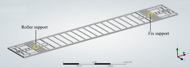
Figure 3 shows the structure with a fix support in the right side of coupler position as a sign with a yellow circle, which constrains all degrees of freedom at that point to simulate a rigid attachment, while roller support of car

body represents a frictionless support condition applied to the left-center pivot with yellow circle sign. This support allows translational movement in the plane while preventing any rotational motion, reflecting a different constraint scenario. Both constraints work to simulate support conditions during passenger body frames under operation as done by Thombare27).
3.6. Loading
Figure 4(a) illustrates a Finite Element Method (FEM) of a passenger train carbody subjected to a compressive load. The compressive load is represented by the red arrow pointing to the right. The magnitude of force about 1000 kN, simulates the structural behavior of the carbody under axial compression conditions when a passenger train is braking31). Figure 4(b) depicts a passenger train carbody subjected to a uniformly distributed vertical load across all frame surfaces31). This simulation represents typical vertical loading conditions experienced during operation, such as passenger weight, equipment, and other additional
features31,32). The red-highlighted areas indicate the

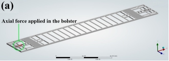


application points of the vertical load. This analysis is critical for understanding the structural behavior, including stress distribution and deformation, enabling the optimization of the welding joint placement to increase safety and lifetime32).
3.7. Meshing
Figure 5 illustrates the meshing method used, which involves discretizing the car body structure into finite elements. The element dimensions are carefully selected, with a finer mesh applied to areas of high-stress concentration or complex geometry and welded structural details, as commonly recommended in FEM analyses of railway and welded structures24,33,34), using hexahedral element as highlighted in the zoomed-in view.
3.8. Stress distribution
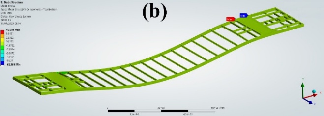
Figure 6(a) and Figure 6(b) present the results of a Finite Element Method (FEM) analysis for the car body structure of a passenger train, highlighting the von Misses and shear stress distribution across the model. The color gradient represents varying stress levels, ranging from lower stress in blue areas to higher stress in red areas. As shown in Figure 6(a), the maximum von Misses stress value, center pivot, and middle span (246.91 MPa and 164. MPa) were located at the middle span of a main beam structure and front of the bolster region, marked by the "Max" label in the zoomed-in inset. Based on Figure 6(b), the maximum shear stress value was identified as 45.51 MPa. This maximum shear stress occurred near the front bolster area on the left and right sides. Both maximum von Misses and shear localized high-stress regions suggest potential structural vulnerability17,18,35) which should be avoided when placing welding joints on the longitudinal main beam. Since fatigue crack initiation in railway structures is strongly governed by local stress concentration at welded joints, relocating welds to low-stress regions is expected to significantly enhance structural durability and service life14,17).
Based on Figure 6(a) and Figure 6(b), several locations can be determined, which should be avoided when determining the location of welded joints, especially welded joints for the longitudinal main beam. Figure 7 shows the regions with the highest stress, which are highlighted by red rectangular boxes, with the maximum stress value occurring near these regions. To ensure structural integrity



and safety, welding joints should be avoided in these high-stress areas35) were marked with red boxes, as they represent zones of potential stress concentration. Instead, the optimal location for welding joints lies in areas with the lowest stress levels36–38), as indicated by the green ellipse color.
3.9. Deformation and displacement analysis
Figure 8 presents the simulated distortion pattern of the passenger train carbody underframe obtained from the Finite Element Method (FEM) analysis. The color contour highlights the distribution of total displacement across the main structural components, including the longitudinal beams, cross beams, and bolster regions. The simulation shows that the maximum distortion occurs near the midspan of the main beams about 34.161 mm, with gradually decreasing deformation toward the coupler and center pivot areas. This deformation pattern suggests that the central sections of the carbody are more flexible under operational loading, whereas the regions close to the supports exhibit higher stiffness and lower displacement.
Fatigue life evaluation methodologies based on displacement and stress concentration have been developed recently, showing improved predictive accuracy for weld root failures19). The observed distortion remains within acceptable thresholds defined by relevant railway design standards, confirming that the structural design meets safety and durability requirements. Furthermore, identifying the areas of highest deformation provides critical insight for optimal weld joint placement. Specifically, weld joints should be positioned in regions exhibiting minimal distortion to prevent premature fatigue failure and maintain structural integrity. This additional analysis supports the earlier stress distribution findings and strengthens the recommendation to place weld joints away from high-stress and high-deformation zones near the midspan and center pivot, favoring locations closer to the bolster region.
The concentration of high von Mises stress at the center pivot and midspan regions can be explained by their structural function as primary load transfer zones, where both bending moments and axial forces converge during operation. This pattern aligns with previous studies by Esderts et al.26) and Sasmito et al.22), which reported similar stress concentrations in comparable welded structures. The identification of lower stress zones between the bolster and midspan not only highlights potential locations for weld joints but also demonstrates the benefit of using detailed FEM analysis to guide practical design choices. Strategically placing weld joints in these low-stress and low-deformation regions can significantly reduce the likelihood of fatigue cracking, prolong service life, and optimize maintenance intervals that are critical for passenger safety and cost efficiency. Furthermore, recognizing these patterns enables designers to anticipate structural behavior under dynamic conditions, supporting more robust and reliable carbody designs.
Although this study focused on identifying low-stress regions for optimal weld joint placement, a direct FEM comparison between the original carbody design and the optimized configuration was not performed. However, previous studies by Livieri and Tovo14,17) have shown that repositioning weld joints from high-stress to low-stress areas typically reduces local stress and strain concentrations, leading to improved fatigue life and structural durability. Including such comparative analysis in future work could further validate the practical benefits of the proposed weld joint placement.
4. Conclusion
Optimal welding joint locations in a passenger train carbody were identified through Finite Element Method (FEM) analysis by evaluating von Mises stress and deformation distributions under operational loading conditions. The results showed that the center pivot and midspan regions experienced high stress values of approximately 246.91 MPa and 164 MPa, respectively, along with maximum deformation reaching about 34.161 mm, indicating these areas should be avoided for weld joint placement. Conversely, regions between the bolster and midspan exhibited lower stress levels below 100 MPa and minimal deformation, making them preferable to enhance fatigue resistance and structural durability. These findings provide simulation-based recommendations that complement existing design practices and support the development of safer and longer-lasting carbody structures. This study was limited to static load conditions without considering dynamic or thermal effects, and future research including these factors and experimental validation is recommended to further refine weld joint placement strategies in railway applications.
Acknowledgments
The authors express their gratitude to Politeknik Perkapalan Negeri Surabaya (PPNS) for the financial support provided for this publication.
References
- E. Bajramović, and F. Islamović, “Assessment of integrity and remaining working life of welded steel structures,” IOP Conf. Ser. Mater. Sci. Eng., 1208 (1) 012011 (2021). doi:10.1088/1757-899x/1208/1/012011.
- M. Sigmund, and J. Spichal, “Possibilities of reducing the number of welds on rail vehicle doors,” Sci. Rep., 12 (1) (2022). doi:10.1038/s41598-022-20837-w.
- P.K. Sen, M. Bhiwapurkar, and S.P. Harsha, “Estimation of fatigue life parameters of an Alumino Thermic weld on UIC60 rail joint using LEFM,” in: J. Phys. Conf. Ser., IOP Publishing Ltd, 2021. doi:10.1088/1742-6596/2115/1/012051.
- H.D. Salman, A. Kamil Sebur, E. Obeid Hassoun, M.K. Sagdatullin, and H. Abdulaziz Abrahem, “Modeling finite element for stress state calculation in combined structures,” in: IOP Conf. Ser. Mater. Sci. Eng., Institute of Physics Publishing, 2020. doi:10.1088/1757-899X/765/1/012063.
- R.R. Patel, D. Valles, G.A. Riveros, D.S. Thompson, E.J. Perkins, J.J. Hoover, J.F. Peters, and A. Tordesillas, “Stress flow analysis of bio-structures using the finite element method and the flow network approach,” Finite Elements in Analysis and Design, 152 46–54 (2018). doi:10.1016/j.finel.2018.09.003.
- Z. Virág, and S. Szirbik, “Modal analysis of optimized trapezoidal stiffened plates under lateral pressure and uniaxial compression,” Applied Mechanics, 2 (4) 681–693 (2021). doi:10.3390/applmech2040039.
- K. Hemmesi, and M. Farajian, “Numerical Welding Simulation as a Basis for Structural Integrity Assessment of Structures: Microstructure and Residual Stresses,” in: Residual Stress Analysis on Welded Joints by Means of Numerical Simulation and Experiments, InTech, 2018. doi:10.5772/intechopen.74466.
- G. Posch, V. Holtsinger, and S.L. Bychkovskii, “Welding of railway wagons: tasks in the area of materials, processes and automation,” Welding International, 29 (3) 213–218 (2015). doi:10.1080/09507116.2014.911416.
- C.T. Ng, C.M. Sonsino, and L. Susmel, “Multiaxial fatigue assessment of welded joints: a review of eurocode 3 and international institute of welding criteria with different stress analysis approaches,” Fatigue Fract. Eng. Mater. Struct., 47 (7) 2616–2649 (2024). doi:10.1111/ffe.14319.
- Mahmood. Aliofkhazraei, and A.S.Hamdy. Makhlouf, “Handbook of materials failure analysis with case studies from the aerospace and automotive industries,” Butterworth-Heinemann, 2016.
- G. Dima, and I. Balcu, “The influence of the path of corner gussets weld seam over the stress concentration factors of the tubular t joints,” Adv. Mat. Res., 1111 67–72 (2015). doi:10.4028/www.scientific.net/amr.1111.67.
- T.A. Netto, M. Igor Lourenço, and B. Adriana Botto, “FATIGUE PERFORMANCE OF REELED RISERS,” 2004. http://www.asme.org/about-asme/terms-of-use.
- M. Matsimbi, P.K. Nziu, L.M. Masu, and M. Maringa, “Topology Optimization of Automotive Body Structures: A review,” 2020. http://www.irphouse.com.
- A. Esderts, J. Willen, and M. Kassner, “Fatigue strength analysis of welded joints in closed steel sections in rail vehicles,” Int. J. Fatigue, 34 (1) 112–121 (2012). doi:10.1016/j.ijfatigue.2011.06.007.
- Y. Kato, M. Takagaki, and T. Yagi, “Design of Car Body by the Method of Structural Optimization,” 2018.
- P. Lacki, and A. Derlatka, “Experimental and numerical investigation of aluminium lap joints made by rfssw,” Meccanica, 51 (2) 455–462 (2016). doi:10.1007/s11012-015-0317-7.
- P. Livieri, and R. Tovo, “Optimization of welded joints under fatigue loadings,” Metals (Basel)., 14 (6) (2024). doi:10.3390/met14060613.
- K. Lipiäinen, A. Ahola, T. Skriko, and T. Björk, “Fatigue strength characterization of high and ultra-high-strength steel cut edges,” Eng. Struct., 228 (2021). doi:10.1016/j.engstruct.2020.111544.
- E.W. Pradana, K. Tateishi, T. Hanji, and M. Shimizu, “Fatigue life evaluation of root failure in welded joints based on displacement around the weld root,” Welding in the World, (2025). doi:10.1007/s40194-025-02293-y.
- J. Schubnell, M. Burdack, N. Hiltscher, P. Weidner, T. Ummenhofer, and M. Farajian, “Fatigue performance of repair-welded and hfmi-treated transverse stiffeners,” Welding in the World, 69 (1) 199–211 (2025). doi:10.1007/s40194-024-01859-6.
- A. Sasmito, Y. Irawadi, and H. Soebagyo, “Analisys of welding crack on the under frame of wagon for cement bags transportation using euro code, measurement and finite element,” MATEC Web of Conferences, 269 03003 (2019). doi:10.1051/matecconf/201926903003.
- Mathweb, “ASTM a36 steel properties,” (2025). https://www.matweb.com/search/datasheet.aspx?MatGUID=afc003f4fb40465fa3df05129f0e88e6 (accessed January 20, 2025).
- M.A. Carolina, P. Marcela, and M. Pedro, “Stress analysis on a ‘l’ shape truss optimization,” International Journal of Advanced Engineering Research and Science, 4 (10) 103–105 (2017). doi:10.22161/ijaers.4.10.17.
- A.G. Diwan, and Y.S. Mahajan, “Study of the effect of various parameters on the result of stress analysis obtained using tetrahedral and hexahedral mesh elements,” Journal of the Chinese Institute of Engineers, Transactions of the Chinese Institute of Engineers,Series A, 40 (2) 101–109 (2017). doi:10.1080/02533839.2017.1287596.
- H. Nakamura, S. Tajima, O. Hazama, and W. Gu, “Automated Fracture Mechanics and Fatigue Analyses Based on Three-Dimensional Finite Element for Welding Components,” 2014. http://asme.org/terms.
- M.A. Zulkifli, K.S. Basaruddin, Y. Abdul Rahim, M. Afendi, P. Gurubaran, and I. Ibrahim, “Three Dimensional Finite Element Analysis on Railway Rail,” in: IOP Conf. Ser. Mater. Sci. Eng., Institute of Physics Publishing, 2018. doi:10.1088/1757-899X/429/1/012010.
- D. Thombare, A. Shinde, and M. Tech, “Finite Element Method for Stress Analysis of Passenger Car Floor,” 2014. https://www.researchgate.net/publication/264992428.
- J.P. Srivastava, P.K. Sarkar, and V. Ranjan, “Contact stress analysis in wheel–rail by hertzian method and finite element method,” Journal of The Institution of Engineers (India): Series C, 95 (4) 319–325 (2014). doi:10.1007/s40032-014-0145-x.
- M. Jukowski, J. Bȩc, and A. Zbiciak, “Finite element analysis of train speed effect on dynamic response of steel bridge,” Open Engineering, 11 (1) 1122–1133 (2021). doi:10.1515/eng-2021-0114.
- M.R. Aalami, A. Anari, T. Shafighfard, and S. Talatahari, “A robust finite element analysis of the rail-wheel rolling contact,” Advances in Mechanical Engineering, 2013 (2013). doi:10.1155/2013/272350.
- BS EN 12663-1:2010, “Railway applications-Structural requirements of railway vehicle bodies-Part 1: Locomotives and passenger rolling stock and alternative method for freight wagons,” 2023. https://standards.iteh.ai/catalog/standards/sist/41dccabd-e420-45b5-baf7-d0a12db3c5c9/sist-en-12663-1-2010a2-2024.
- L.A. Morscheck, and J.J. Roller, “Stress testing of a new north american passenger locomotive truck frame in accordance with international union of railways (uic) code,” 2013. http://www.asme.org/about-asme/terms-of-use.
- R.C. Ariesta, A. Zubaydi, A. Ismail, and T. Tuswan, “Damage evaluation of sandwich material on side plate hull using experimental modal analysis,” in: Mater. Today Proc., Elsevier Ltd, 2021: pp. 2310–2314. doi:10.1016/j.matpr.2021.04.293.
- M.S. Akbar, A.R. Prabowo, D.D.D.P. Tjahjana, and T. Tuswan, “Analysis of plated-hull structure strength against hydrostatic and hydrodynamic loads: a case study of 600 teu container ships,” J. Mech. Behav. Mater., 30 (1) 237–248 (2021). doi:10.1515/jmbm-2021-0025.
- W. Jo, I. Woo, Y. Mikami, and G. An, “Residual stress characteristics in spot weld joints of high-strength steel: influence of welding parameters,” Applied Sciences (Switzerland), 14 (24) (2024). doi:10.3390/app142411971.
- “EN 1993-1-2: Eurocode 3: Design of steel structures - Part 1-2: General rules - Structural fire design,” 1993.
- T. Skriko, K. Lipiäinen, A. Ahola, H. Mettänen, and T. Björk, “Fatigue strength of longitudinal load-carrying welds in beams made of ultra-high-strength steel,” J. Constr. Steel Res., 179 (2021). doi:10.1016/j.jcsr.2021.106563.
- N. Nasir, M. Khairul, A.A. Razab, and S. Mamat, “Review on Welding Residual Stress,” 2016. https://www.researchgate.net/publication/303788758.