
Abstract
This paper presents a computationally efficient actuator line-based CFD approach for simulations of diffuser-augmented wind turbines (DAWTs) using the OpenFOAM framework. A pressure-based actuator line model is applied to both the rotor and the diffuser, enabling accurate representation of rotor–diffuser interaction without explicitly resolving the diffuser geometry. Numerical simulation results demonstrate that the proposed framework accurately predicts DAWT performance and captures diffuser-induced flow acceleration and pressure redistribution. The method provides a computationally efficient and physically consistent tool for engineering-oriented DAWT analysis, parametric studies, and design optimization.
Keywords: Actuator line model, CFD, DAWT, OpenFOAM
Outline
1. Introduction
Diffuser-augmented wind turbines (DAWTs), as illustrated in Figure 1, have been widely studied as a method to enhance power extraction by increasing the mass flow through the rotor. Although the Betz limit applies to ideal bare rotors in unbounded flow, diffuser-augmented configurations can theoretically exceed this limit when the power coefficient is defined based on the rotor swept area1-4). In principle, diffuser structures can be applied to any conventional wind turbines5). DAWTs were introduced at the Innovative Wind Systems Conference in 1979 and recognized as a promising approach to enhance wind turbine power output6). Early theoretical and experimental investigations demonstrated that shrouds or diffusers can augment turbine performance by sustaining sub-atmospheric pressure at the rotor exit, thereby drawing additional flow through the turbine7). A one-dimensional analysis predicted that a duct with an area ratio of 3.5 and 15% pressure loss could increase maximum power by about 65%8). A rigorous theoretical assessment later clarified that simple cubic scaling of the locally accelerated wind speed is not applicable to DAWTs, and that performance gains are constrained by diffuser-induced back pressure and the effective control volume9). This work established an important theoretical framework and an upper bound for DAWT performance.
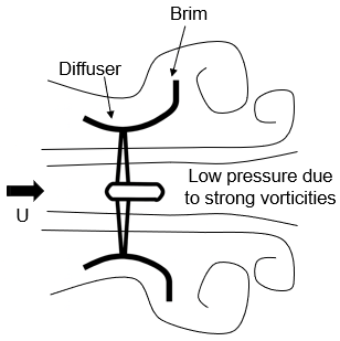
Subsequent experimental studies, particularly those conducted at Kyushu University, clarified the physical mechanisms responsible for practical DAWT performance enhancement10-13). It was shown that the addition of a flanged (brimmed) diffuser generates strong vortical structures downstream of the diffuser exit, forming a low-pressure region that significantly increases the mass flow rate through the rotor and leads to substantial power augmentation, as illustrated in Figure 210,11).
Detailed measurements further demonstrated that the presence of a flanged diffuser strongly modifies rotor wake development and tip vortex behavior12). More application-

oriented investigations confirmed that appropriately designed diffusers can achieve meaningful performance gains under realistic operating conditions13). Collectively, these studies establish the experimental and theoretical foundation of DAWTs and highlight the central role of diffuser-induced pressure effects in performance enhancement.
Computational approaches have played a central role in understanding diffuser-augmented wind turbines (DAWTs), particularly in quantifying the relationship between shroud-induced mass flow acceleration and power augmentation14-16). Early CFD studies combined actuator disk models, including those based on blade element momentum (BEM) theory, with Navier–Stokes solvers to capture rotor–diffuser coupling and showed that augmentation scales with increased mass flow and diffuser-induced pressure recovery17-19).
To improve physical fidelity, Reynolds-Averaged Navier–Stokes (RANS) formulations have been widely applied to shrouded turbine configurations. High-resolution axisymmetric and three-dimensional RANS simulations investigated mass-flow capture, boundary-layer separation, rotor–shroud interaction, and augmentation limits under various geometric and operating conditions20-23). These studies demonstrated that augmentation ratios approaching 1.9 can be achieved under attached-flow conditions, while also highlighting sensitivity to rotational speed and separation behavior. Large-eddy simulation (LES) approaches have further been used to examine turbine loading and wake development under realistic atmospheric turbulence conditions, emphasizing the role of coherent structures in power production and wake dynamics24). In parallel, semi-analytical momentum-based models extended classical one-dimensional theory to nozzle–diffuser augmented configurations and showed that optimal thrust coefficients deviate from the classical 8/9 value depending on back-pressure conditions25). Although suitable for preliminary design, such models cannot resolve detailed rotor–diffuser–wake interactions.
The actuator line model (ALM) was introduced to bridge the gap between actuator disk formulations and fully blade-resolved simulations by representing rotating blades as body forces distributed along lines within a Navier–Stokes solver26). Unlike actuator disk approaches, ALM accounts for discrete blade effects and resolves the trailed vorticity in the wake while avoiding the high computational cost of geometry-resolved CFD. Early implementations coupled ALM with three-dimensional incompressible Navier–Stokes solvers, distributing lift and drag forces using a Gaussian regularization kernel to avoid numerical singularities18,26). The approach was further developed within the EllipSys3D framework and applied extensively to wake simulations under uniform, sheared, and turbulent inflow conditions, demonstrating good agreement with experimental data in terms of power prediction and wake development27,28). A key numerical aspect of ALM is the choice of the smoothing length scale ε used in the Gaussian force projection. The selected ε directly affects induced velocities, wake structure, and blade loading prediction. Systematic investigations showed that ε should scale with the local chord length rather than purely with grid spacing, in order to maintain physical consistency of the force distribution29). Analytical considerations based on the linearized Euler equations further demonstrated that the optimal smoothing width corresponds to approximately 14–25% of the local chord length and depends only weakly on angle of attack30). These studies clarified that accurate ALM simulations require both a physically meaningful smoothing length and sufficient grid resolution near the actuator line. In particular, the mesh spacing must adequately resolve the Gaussian kernel to avoid underprediction of circulation and incorrect wake roll-up behavior29,30). The applicability of the actuator line model within industrial CFD frameworks has been demonstrated through its implementation in OpenFOAM for simulations of the NREL Phase VI and NREL 5 MW turbines, showing good agreement with experimental load and power measurements while highlighting the strong sensitivity of blade-root and tip load predictions to the choice of Gaussian smoothing width31).
Despite its demonstrated accuracy and computational efficiency, the conventional ALM remains dependent on isotropic force projection strategies and empirical smoothing parameters, which are known to be effective for rotor modeling but may limit applicability to more complex geometries. This sensitivity motivates further refinement of actuator-based formulations to improve physical consistency and robustness across different blade geometries and operating conditions.
To overcome the limitations of conventional actuator line models, advanced actuator line formulations have been developed to improve the physical consistency of force projection and velocity sampling32). An advanced actuator line framework was introduced that incorporates anisotropic force projection functions and integral based velocity sampling, leading to significant improvements in blade load prediction and near wake resolution while maintaining computational efficiency32).
More recently, the advanced actuator line concept has been extended to fully DAWT configurations, showing that anisotropic actuator-based modeling can successfully reproduce diffuser induced flow acceleration and wake characteristics without explicitly resolving the diffuser geometry33). This implementation was developed within the high order PyFR framework, demonstrating the potential of the advanced actuator line approach for high fidelity DAWT simulations. However, the application of such advanced actuator formulations within widely used industrial CFD platforms, such as OpenFOAM, and their validation in an engineering-oriented context remain limited, motivating the present work.
In the present study, the advanced actuator line framework originally developed by Liang et al33). in the PyFR environment is implemented and extended within the OpenFOAM platform. The main contribution of this work lies in adapting the anisotropic force projection and diffuser actuator formulation to a widely used industrial CFD framework, enabling practical and scalable simulations of diffuser-augmented wind turbines. The proposed implementation is systematically validated against canonical benchmark cases, including rotor performance and translating wing configurations, and further applied to full DAWT simulations. This approach provides a unified and computationally efficient framework for engineering-oriented DAWT analysis, while maintaining consistency with previously developed high-fidelity actuator formulations. The remainder of this paper presents the numerical formulation, validation procedures, and results obtained using this framework.
2. Methodology
2.1. Governing Equations
The incompressible Navier–Stokes equations with actuator line body forces are solved using OpenFOAM26). The governing equations are given as:


where f represents the body force introduced by the ALM.
LES is employed to resolve the unsteady wake dynamics of the diffuser-augmented wind turbine. In the LES framework, the incompressible Navier–Stokes equations are spatially filtered and can be written as:


where ũ and p̃ denote the filtered velocity and pressure, respectively. The subgrid-scale (SGS) stress tensor τsgs accounts for the effects of unresolved turbulence. The SGS stresses are modeled using the Smagorinsky model. The actuator line body forces f are applied directly to the resolved velocity field and interact with the resolved turbulent structures. A second order accurate temporal discretization is adopted, and the time step is selected to maintain the Courant number below 0.9. Local mesh refinement is applied in the rotor and diffuser region to ensure adequate resolution of the dominant turbulent length scales.
2.2. ALM
The ALM is employed to represent the aerodynamic effects of wind turbine blades without explicitly resolving the blade geometry. In the ALM framework, each blade is discretized into a series of actuator points along the spanwise direction, as illustrated in Figure 3. At each actuator point, aerodynamic forces are computed based on the local flow conditions and subsequently projected onto the Eulerian grid as body forces. This approach enables accurate prediction of blade-induced flow features while maintaining a significantly reduced computational cost compared with fully resolved simulations.
2.3. Blade standard isotropic 3D Gaussian kernel
In the ALM, each rotor blade is discretized into a series of

actuator elements along the spanwise direction. At each actuator element, the aerodynamic force is computed based on the local relative velocity and airfoil characteristics, and subsequently introduced into the flow field as a body force. The aerodynamic force vector acting on an actuator element is given by

where ρ is the air density, Urel is the magnitude of the local relative velocity, c denotes the local blade chord length, CL and CD are the lift and drag coefficients obtained from airfoil data tables, and eL and eD represent the unit vectors in the lift and drag directions, respectively. Ftip is the tip loss correction factor. The local relative velocity magnitude is defined as

where Ux is the axial velocity component, Uaz is the azimuthal (tangential) velocity component sampled from the flow field, Ω denotes the angular velocity of the rotor, and r is the radial distance from the rotor axis to the actuator element. The flow velocity components r and Uaz are obtained by sampling the resolved velocity field at the actuator element location using a Gaussian-weighted interpolation, ensuring a smooth and numerically stable evaluation of the local inflow conditions. To account for the finite blade length and the associated reduction of aerodynamic loading near the blade tip, a tip loss correction factor is applied. In this study, the tip loss correction is directly applied to the lift and drag forces. The tip loss factor is expressed as

where NB is the number of rotor blades, Rrotor denotes the rotor radius, φ is the local inflow angle, and gk is an empirical correction coefficient. The aerodynamic forces computed at the actuator elements are introduced into the governing equations as distributed body forces. An isotropic Gaussian projection function is adopted to smoothly distribute the actuator forces onto the surrounding Eulerian grid points. The isotropic Gaussian projection kernel is defined as

where

where (x0, y0, z0) denotes the spatial location of the actuator element, and ε is the projection width parameter controlling the spatial extent of force smoothing. The resulting body force applied to the flow field is given by

where Nele is the total number of actuator elements, and fi represents the aerodynamic force vector computed at the i-th actuator element. Through this isotropic Gaussian projection, the blade-induced forces are smoothly distributed in space, avoiding numerical singularities and ensuring stable coupling between the ALM and the flow solver.
2.4. Diffuser anisotropic Gaussian projection
The diffuser is a stationary structure with a circumferentially continuous geometry, whose aerodynamic influence differs fundamentally from that of rotating rotor blades. To model the diffuser-induced aerodynamic loading without explicitly resolving the diffuser geometry, a ring-based actuator line formulation is adopted. The diffuser surface is discretized into a series of actuator elements distributed circumferentially along multiple axial rings, allowing the diffuser loading to be applied in a distributed and physically consistent manner.
Figure 4 illustrates the force analysis and geometric definition of a diffuser actuator element33).
Based on these velocity components, the magnitude of the local relative velocity is defined as


which represents the effective inflow speed impinging on the diffuser actuator element.
The inflow angle φ in Equation 12 determines the orientation of the diffuser-induced aerodynamic force, while the relative velocity magnitude Urel governs the force magnitude through the diffuser force formulation.

The aerodynamic loading acting on the diffuser is assumed to be drag-dominated. Accordingly, the diffuser-induced force is assumed to act opposite to the local inflow direction.
The circumferential position of each actuator element is described by the angle θ, while the orientation of the force is determined by the direction of the relative velocity vector. The resulting force can be decomposed into streamwise and radial components, where the streamwise component contributes to axial momentum redistribution and flow acceleration inside the diffuser, and the radial component is associated with the pressure loading along the diffuser surface.
The aerodynamic force acting on an individual diffuser actuator element is expressed as

Here, the term wdif represents an effective weighting factor associated with the diffuser element, accounting for the local surface extent represented by the actuator element. The coefficient Cdif serves as an overall diffuser loading coefficient, while CL,dif and CD,dif denote the lift-like and drag-like force coefficients associated with the diffuser element, respectively.
The unit vectors eL,dif and eD,dif define the directions of the lift-like and drag-like components in the local coordinate system, as illustrated in Figure 4.
Although the diffuser does not generate aerodynamic lift in the classical sense, this formulation enables a flexible decomposition of the resultant diffuser-induced force while ensuring consistency with the resultant force direction inferred from the pressure distribution along the diffuser surface. The diffuser-induced loading is not uniformly distributed along the circumferential direction. To account for this effect, an angular weighting function gdif(θ) is introduced, which modulates the magnitude of the diffuser force according to the circumferential position of the actuator element. The angular weighting function is derived from the pressure distribution along the diffuser surface and is expressed as

where θ denotes the angular location corresponding to the peak diffuser loading, ω controls the angular extent of the effective loading region, κ is a skewness parameter, and ϕ and Φ represent the standard normal probability density function and cumulative distribution function, respectively. This formulation enables flexible control of both the spatial extent and asymmetry of diffuser loading.
To ensure that the total diffuser-induced force remains consistent regardless of the angular weighting distribution, the diffuser force coefficient is normalized as

The coefficient Cdif serves as a normalization factor to ensure that the total diffuser-induced force remains consistent under different angular weighting distributions and projection parameters.
The aerodynamic force parameters of the diffuser are constructed based on numerical simulations rather than prescribed empirically. Specifically, a representative spanwise section of the diffuser is extracted and simulated using a fully resolved CFD model under a fixed inflow condition. The pressure distribution on the diffuser surface, particularly on the upper surface, is obtained from the simulation results and exhibits a pronounced asymmetric behavior along the circumferential direction. To incorporate this non-uniform characteristic into the actuator-based formulation, the pressure distribution is fitted using a skewed normal distribution. Based on this fitting, the angular weighting function gdif(θ) is constructed to represent the circumferential variation of diffuser-induced loading.
Furthermore, to characterize the aerodynamic response under different inflow directions, the same diffuser section is rotated around its geometric center and simulated in OpenFOAM under various effective angles of attack. From these simulations, the corresponding lift-like and drag-like coefficients, CL,dif and CD,dif, are extracted.
In this way, the diffuser force model incorporates both the circumferential variation of pressure loading and the directional characteristics of the aerodynamic force, providing a physically consistent representation of diffuser-induced effects within the actuator line framework.
The aerodynamic forces generated by the diffuser actuator elements are introduced into the flow field as distributed body forces. The resulting body force density is obtained by convolving the discrete actuator forces with a diffuser-specific projection kernel,

where Nele denotes the total number of diffuser actuator elements.
To accurately represent the directional characteristics of diffuser-induced loading, an anisotropic projection function is employed. The local coordinate system used for force projection is illustrated in Figure 5, where the tangential direction t follows the diffuser surface and the wall-normal direction w is perpendicular to the surface. This coordinate system enables independent control of force spreading along and normal to the diffuser surface.
The anisotropic projection kernel is defined as

where xt and xw denote the local tangential and wall-normal coordinates, (xt,0, xw,0) is the reference position of the actuator element, and εt and εw are the projection widths in the tangential and wall-normal directions, respectively. The projection widths in the tangential and wall-normal directions are defined as εt=atT and εw=awW, respectively. These widths represent the characteristic Gaussian diffusion lengths used to distribute the diffuser-induced forces along and normal to the diffuser surface.
Here, T and W denote the local thickness and width of the diffuser actuator element, which define the geometric support of the force application. The coefficients at and aw are dimensionless projection factors that control the spatial extent of force spreading in the tangential and wall-normal directions, respectively.
In the present study, the values of at and aw are both set to 0.8, following the parameter range suggested by Liang33), with values selected to ensure numerical stability and physical localization in the OpenFOAM framework. This choice ensures a balanced force distribution that maintains numerical stability while preserving the physical localization of diffuser-induced loading.
In addition to the anisotropic force projection, the diffuser brim is implicitly represented through a streamwise distance constraint applied to the projection kernel. Specifically, a distance constraint is imposed in the streamwise x direction, such that the projected forces from each diffuser actuator element are limited to a prescribed maximum axial distance. By restricting the projection of the small circular arc elements near the diffuser exit to a finite streamwise extent, the aerodynamic influence of the diffuser brim is naturally formed. This treatment effectively concentrates the diffuser-induced loading in the

vicinity of the brim region without explicitly modeling the brim geometry. As a result, the flow acceleration and pressure redistribution associated with the diffuser brim are captured through the localized force projection, while maintaining the computational efficiency and numerical robustness of the actuator line framework.
As illustrated in Figure 5, this anisotropic formulation allows the diffuser-induced forces to be preferentially distributed along the diffuser surface while remaining tightly confined in the wall-normal direction. Compared with isotropic Gaussian projection commonly used for rotor blades, the proposed approach prevents nonphysical force spreading and provides a physically consistent representation of diffuser-induced aerodynamic loading.
3. Validation
3.1. Grid independence and validation of the rotor ALM
Before validating the diffuser ALM, the numerical behavior of the conventional rotor ALM is first assessed through a grid independence study and comparison with experimental data. This step serves as a baseline validation to ensure that the predicted rotor performance is not influenced by grid resolution effects.
The computational domain employs a non-uniform mesh with local refinement applied in the rotor region, as shown in Figure 6. The finest grid resolution is prescribed in the vicinity of the rotor disk to accurately capture the actuator line force projection and near-wake development. Moving away from the rotor region, the grid spacing is gradually coarsened to reduce the overall computational cost while maintaining numerical stability. This mesh design ensures that the actuator line forces are resolved on sufficiently fine cells, which is essential for reliable ALM simulations.
The rotor ALM implemented in OpenFOAM is first validated against experimental measurements and

numerical results available from the Norwegian University of Science and Technology (NTNU) wind turbine benchmark34). The experimental configuration of the NTNU rotor tests is summarized in Table 1, and the corresponding wind tunnel layout and rotor placement are illustrated in Figure 7.
All geometric dimensions, inflow conditions, and rotor positioning adopted in the present actuator line simulations strictly follow the experimental setup. This combined description provides a complete definition of the validation conditions and enables a direct comparison between numerical and experimental rotor performance.
To assess the sensitivity of the rotor ALM to grid resolution, a grid independence study is performed using three mesh configurations with increasing refinement in the rotor region. Figure 8 shows the comparison of the predicted CP obtained using coarse, medium, and fine meshes. Computational set up are summarized in Table.2.
The results indicate that the predicted CP curves collapse closely over the entire TSR range. In the primary operating range near the optimal TSR (TSR = 4–7), the deviation between the medium and fine meshes remains within
Table 1: Experimental configuration of the NTNU rotor tests
| Airfoil | NREL S826 |
|---|---|
| Free stream wind speed | 10 m/s |
| Rotor diameter | D = 0.894 m |
| Height of rotor centre | Z = 0.817 m |
| Desighnd peak tip-speed ratio (TSR) | 6 |
approximately 2–7%, while the peak power coefficient and its location remain nearly unchanged across all tested grid resolutions. Larger differences are only observed in the high-TSR regime, where the flow becomes increasingly sensitive to numerical resolution. This demonstrates that the rotor ALM predictions are weakly sensitive to grid refinement once sufficient resolution is provided in the vicinity of the actuator line. Based on these results, the medium-resolution mesh is selected for all subsequent simulations, providing a satisfactory balance between numerical accuracy and computational efficiency.
Figure 9 presents the comparison of the predicted CP as a function of the TSR with the NTNU experimental data and a range of reference CFD simulations reported in the literature34,35). The predicted power coefficient shows good agreement with the experimental data, particularly near the optimal TSR. In the main operating range (TSR = 4–8), the deviation generally remains within 10%, while it decreases to within approximately 3% near the optimal TSR range of TSR = 6–7, indicating that the peak performance is accurately captured. Larger discrepancies are observed at low and high TSR conditions. At low TSR, the flow is dominated by stall and separation effects, which are not fully resolved by the actuator line model. At high TSR, the deviation is mainly attributed to the sensitivity of induced velocity modeling and tip-loss correction. Overall, the model captures the main performance trends and peak characteristics with good accuracy. Notably, the present results show comparable accuracy to higher fidelity actuator-line-based LES approaches, while maintaining significantly reduced computational cost.
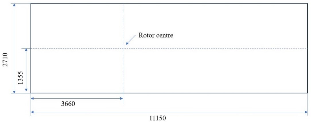
Table 2: Summary of computational setup for rotor validation
| Case | Coarse | Medium | Fine |
|---|---|---|---|
| Cell number | 90k | 716k | 1026k |
| Min cell size | 0.04 | 0.02 | 0.01 |
| Time step | Adjust time step | ||
| Max Courant number | 0.9 | ||
| CPU cores | 8 | ||
| Physical time | 1s | 1s | 1s |
| Clock time | 1000s | 3600s | 11000s |


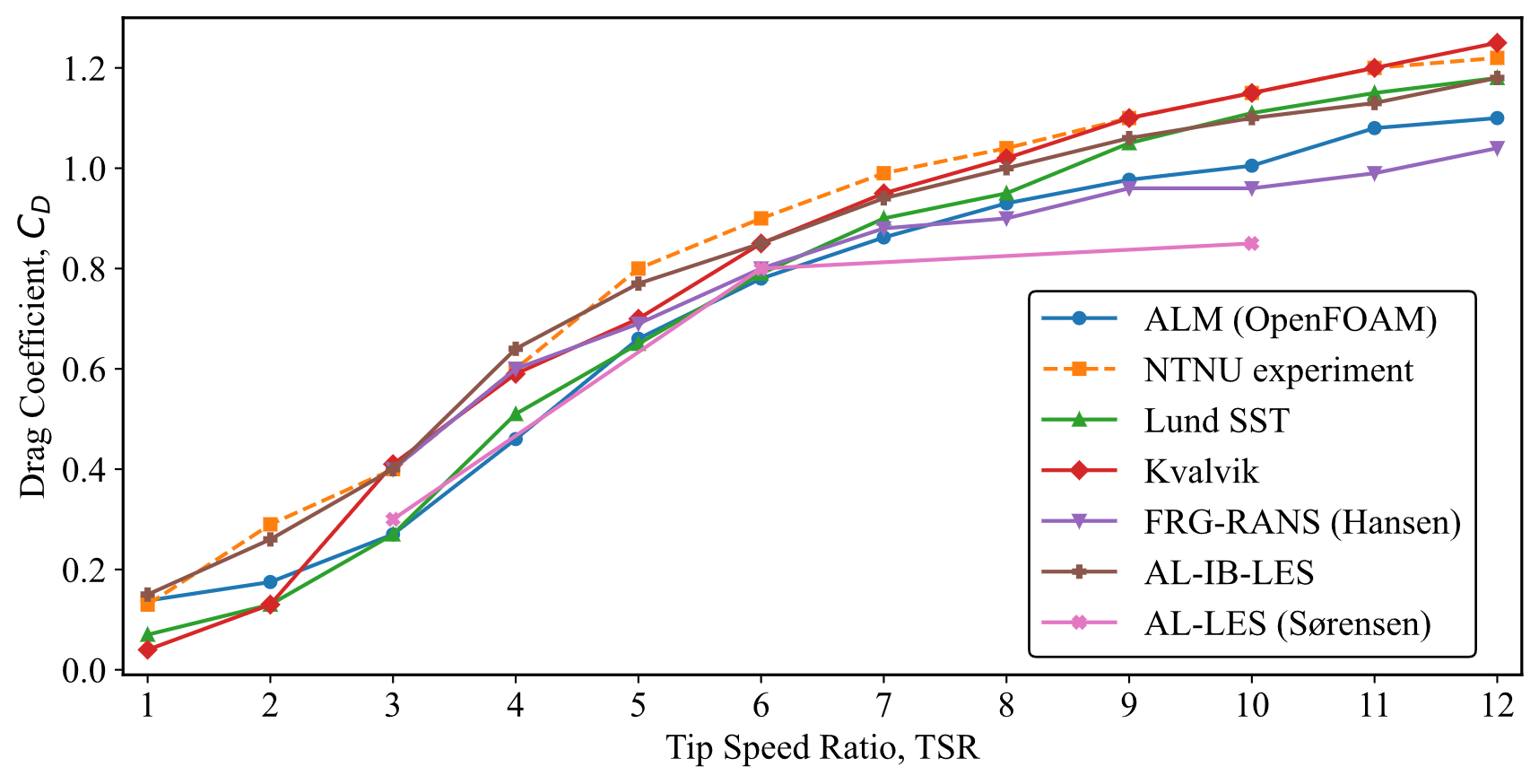
A quantitative comparison shows that the predicted CD agrees well with the experimental data over the main operating range, as shown in Figure 10. The deviation is generally within approximately 5–12% for most TSR conditions, indicating that both the magnitude and trend of the rotor drag are well reproduced. Larger discrepancies are observed at very low TSR conditions, where flow separation and unsteady effects become significant and are not fully resolved by the actuator line model. Nevertheless, the present predictions remain within the range of previously reported numerical results, demonstrating that the rotor loading is reliably represented.
3.2. Translating wing configuration
To validate the proposed diffuser actuator line formulation with anisotropic force projection, a translating wing benchmark is employed. The test case consists of a finite-span wing with a quarter-circular cross section, translating at a constant velocity in an otherwise quiescent flow field. This configuration serves as a simplified analogue of a diffuser segment, allowing the aerodynamic effects of a curved, stationary structure to be isolated and examined without the complexity introduced by rotor rotation.
Figure11 illustrates the computational setup. The wing spans a length S in the spanwise direction, and the computational domain dimensions are defined relative to S to minimize boundary effects. The wing is positioned sufficiently far from the domain boundaries, and the mesh is locally refined in the vicinity of the wing to adequately resolve the actuator force projection and the near-field flow response. At the inlet, a uniform velocity profile is prescribed with a fixed value boundary condition, while the pressure is set to zero gradient. At the outlet, a fixed pressure condition is applied, and the velocity is treated with zero gradient. The lateral and top boundaries are defined as symmetry planes to minimize confinement effects. The turbine rotor and diffuser are modeled using actuator-based body forces implemented through the fvOptions framework.
To assess the numerical robustness of the proposed diffuser ALM, a grid independence study is conducted for the translating wing configuration. Figure12 shows the Ux sampled along the vertical centerline at the mid-span location (illustrated in Figure13) for three different mesh

resolutions. The velocity profiles obtained on the coarse, medium, and fine meshes exhibit very similar overall shapes, and the computational setups are summarized in Table 3. All three meshes capture the pronounced velocity deficit near the wing location, followed by the strong flow acceleration beneath the wing and the gradual downstream recovery. The deviation between the medium and fine meshes in the main flow regions remains within approximately 5%, while the peak velocity differs by less than approximately 2%. In addition, the location of the minimum velocity, indicated by the dashed vertical line, remains nearly unchanged across the different grid resolutions. These results indicate that the selected mesh provides sufficient resolution for accurately capturing the primary flow features.
Minor differences are observed in the magnitude of the minimum velocity and the sharpness of the velocity gradient near the wing. As the mesh is refined, the velocity deficit becomes slightly deeper and the gradient steeper, reflecting improved resolution of the localized force projection region.
However, these differences are confined to a narrow region near the wing and do not affect the overall acceleration trend or the downstream recovery behavior. The close agreement among the velocity profiles demonstrates that the translating wing results obtained with the diffuser ALM are weakly sensitive to grid refinement once sufficient resolution is provided in the vicinity of the actuator elements. Based on these observations, the medium mesh is considered adequate for accurately capturing the diffuser-induced flow acceleration while maintaining reasonable computational cost.
Figure 14 presents a qualitative comparison of the time-averaged velocity fields predicted by three different modeling approaches: (i) a fully resolved model (FRM), (ii) an anisotropic ALM implemented in PyFR, and (iii) the present OpenFOAM-based ALM.
All three approaches capture the characteristic flow features induced by the translating wing, including the

pronounced velocity deficit in the immediate wake and the acceleration of the incoming flow beneath the wing. The present ALM reproduces both the spatial extent and the overall intensity of the velocity perturbations observed in the FRM results. Compared with the PyFR-based actuator line simulation, the predicted wake structure and flow acceleration show close qualitative agreement, indicating that the proposed anisotropic projection strategy successfully captures the dominant diffuser-like aerodynamic effects. Minor discrepancies are observed in the near-field region, which are expected due to the absence of explicitly resolved geometry in the actuator line formulations and the smoothing effect introduced by force projection.
A quantitative comparison is provided in Figure 15, which shows the streamwise velocity component Ux sampled along the vertical centerline at the mid-span location of the wing. The FRM exhibits a sharp velocity deficit near the wing location, followed by rapid flow recovery downstream. Both ALMs reproduce the overall shape of the velocity profile, including the location of the minimum velocity and the subsequent acceleration region. The present OpenFOAM-based ALM successfully captures the acceleration of the incoming flow beneath the wing, which is a key physical mechanism associated with diffuser-induced performance enhancement. The magnitude and

Table 3: Summary of computational setup for wing validation
| Case | Coarse | Medium | Fine | ||
|---|---|---|---|---|---|
| Cell number | 745k | 1249k | 1805k | ||
| Min cell size | 0.04 | 0.02 | 0.01 | ||
| Time step | Adjust time step | ||||
| Max Courant number | 0.9 | ||||
| CPU cores | 8 | ||||
| Physical time | 1s | 1s | 1s | ||
| Clock time | 3000s | 6000s | 13000s | ||

From left to right: (i) FRM, (ii) anisotropic ALM implemented in PyFR, and (iii) OpenFOAM-based ALM

spatial extent of this acceleration are in close agreement with the PyFR-based actuator line results.
Although the ALM results exhibit smoother velocity gradients compared with the FRM, the essential flow features are preserved. The deviation in the main flow regions remains within approximately 5–10%, while larger local discrepancies are observed near the velocity minimum due to the smoothing effect of the distributed body-force representation. The peak velocity and its location are also well captured, with only minor deviations. Overall, the diffuser actuator line model provides an accurate and computationally efficient representation of diffuser-induced momentum redistribution.
4. Results and Discussion
4.1. Validation result discussion
The results of the translating wing validation demonstrate that the proposed diffuser ALM is capable of reproducing both qualitative and quantitative flow features associated with curved diffuser-like structures. The close agreement with the PyFR-based ALM confirms the consistency of the anisotropic projection strategy across different numerical frameworks. At the same time, the comparison with the FRM shows that the essential diffuser-induced flow acceleration mechanism is retained despite the reduced-order nature of the actuator line approach. These findings provide strong support for the application of the proposed diffuser ALM to full diffuser-augmented wind turbine configurations.
4.2. Full DAWT performance
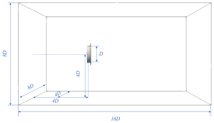
To investigate the aerodynamic performance of the full DAWT, simulations were carried out using a computational domain specifically designed to minimize blockage effects and ensure sufficient wake development, as illustrated in Figure16.
The full DAWT simulations employ the same mesh refinement strategy as that validated in the single-rotor and translating wing cases. A three-level nested mesh refinement is adopted, with the finest grid concentrated in the rotor diffuser region to accurately resolve the actuator-induced flow features as shown in Figure17. Additional refinement is applied downstream to properly capture the wake recovery and velocity deficit evolution. This mesh strategy has been verified to be mesh-independent in the validation studies, and is therefore directly extended to the full DAWT simulations to ensure both numerical accuracy and computational efficiency.
The DAWT system, consisting of a CiB5 type diffuser coupled with a 1 m diameter rotor using the MEL airfoil, is positioned at the geometric center of the domain in both the vertical and spanwise directions. This placement avoids asymmetrical boundary influences and maintains consistency with the assumptions of uniform inflow conditions. The rotor axis is aligned with the streamwise direction, and the diffuser is concentrically mounted around the rotor.
At the inlet, a uniform velocity profile corresponding to the prescribed freestream velocity is imposed, while a zero-gradient condition is applied at the outlet. Slip or symmetry boundary conditions are used on the lateral and top boundaries to further reduce blockage and wall-induced effects. All simulations are conducted using the ALM framework implemented in OpenFOAM, with the diffuser forces introduced via the proposed anisotropic actuator formulation described in Section 2.
This configuration serves as the baseline setup for the full DAWT results presented in the following sections,
including power coefficient comparisons under different inflow velocities and detailed flow field analyses.
Figure 18 and Figure 19 compare the predicted CP as a function of TSR for the full DAWT configuration against the corresponding experimental measurements at U∞= 8 m/s and U∞= 10 m/s, respectively. In both cases, the experimental campaign focused on TSR values around the optimal operating condition, and therefore the measurements are available mainly in the vicinity of the performance peak.
For both inflow speeds, the present OpenFOAM-based full-DAWT ALM reproduces the experimentally observed peak region with high fidelity. The predicted curves follow the same trend as the measurements within the tested TSR interval, and the optimal TSR is captured consistently. Moreover, the magnitude of in the peak region shows maximum 7% deviations from the experimental values, indicating that the combined aerodynamic effects of the interaction between the rotor and the diffuser, including the flow acceleration induced by the diffuser and the rotor’s loading response, are accurately represented by the proposed modeling framework. A key observation is that the model maintains the correct peak TSR for both U∞= 8 m/s and U∞=10 m/s. This is non-trivial for DAWT simulations, because the optimal TSR depends on the coupled behavior of (i) the rotor aerodynamic loading and (ii) the diffuser/brim-induced modification of the incoming mass flow and pressure field. The agreement therefore supports the physical consistency of the full-DAWT actuator representation, rather than merely matching a single operating point. Comparing the two inflow speeds, the experimental peak CP levels are similar, while the predicted curves exhibit only weak dependence on inflow speed in the vicinity of the optimum TSR. This behavior is expected for geometrically identical configurations operating in comparable Reynolds-number regimes, where the DAWT performance around the design point is largely governed by diffuser-induced acceleration and rotor aerodynamic efficiency. The fact that the model captures the peak region for two distinct inflow speeds using the same modeling parameters provides additional confidence in the robustness of the framework.
The numerical results extend over a wider TSR range than the available measurements. At low TSR, the predicted CP remains small, followed by a rapid increase as the rotor approaches its optimal operating regime. At higher TSR, a gradual reduction in CP is observed. Although no experimental points are available in these regions for direct comparison, the predicted overall behavior is consistent with typical DAWT performance characteristics: the efficiency rises toward an optimum TSR and decreases as the rotor becomes increasingly under-loaded and the wake structure changes. Given that the experimental data are limited to the peak region, the present results provide a physically plausible performance envelope that can be used to guide subsequent parametric studies and optimization.
The remaining small discrepancies between simulation and experiment near the peak region may be attributed to several factors. First, the actuator representation inherently smooths force application compared with fully resolved geometry, which can slightly modify near-wall pressure gradients and local separation behavior in the diffuser/brim region. Second, experimental uncertainty associated with inflow non-uniformity, blockage, and measurement


repeatability may also contribute to small deviations. Finally, the exact rotor–diffuser alignment and geometric tolerances in the experimental setup can influence peak performance, particularly for compact DAWT configurations. Despite these factors, the close agreement in both trend and peak performance demonstrates that the proposed OpenFOAM-based full-DAWT actuator line framework can accurately predict DAWT power characteristics at practical inflow speeds.
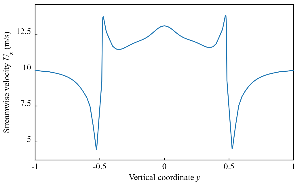
As shown in Figure 20(a), a pronounced flow acceleration inside the diffuser is clearly observed. The streamwise velocity within the diffuser exceeds the freestream value, indicating the strong suction effect induced by the diffuser geometry. This accelerated inflow persists across the rotor plane, confirming the diffuser’s role in enhancing the effective inflow velocity experienced by the rotor. As shown in Figure 21, the streamwise velocity increases from the incoming velocity of approximately 10 m/s to peak values exceeding 13 m/s near the diffuser throat, indicating a strong diffuser-induced acceleration effect. Downstream of the rotor, a locally elevated centerline velocity is observed, which is attributed to the absence of an explicit nacelle model in the present simulations. Despite this local feature, the overall wake structure exhibits a gradual velocity recovery and a delayed wake expansion compared with a bare rotor configuration.
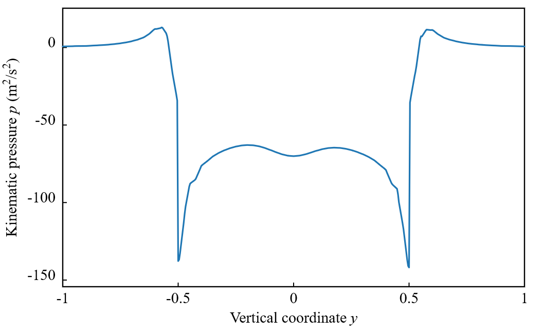
The corresponding pressure field is shown in Figure 20(b). A distinct low-pressure region develops near the diffuser throat and along the inner diffuser surface, which drives the acceleration of the incoming flow through the rotor plane. The pressure profile in Figure 22 shows a pronounced pressure deficit near the inner diffuser surface, with the minimum pressure reaching approximately −140 m²/s², which is consistent with the accelerated flow observed in the velocity field. This pressure deficit is followed by a pressure recovery downstream of the diffuser exit, consistent with diffuser-induced expansion and wake mixing. The spatial correlation between the low-pressure regions and the accelerated velocity field highlights the dominant role of pressure gradients in governing the flow behavior of the DAWT.
Overall, the combined velocity and pressure fields demonstrate that the present ALM-based full DAWT model successfully captures the key aerodynamic mechanisms of DAWTs, including diffuser-induced suction, inflow acceleration at the rotor plane, and wake modulation downstream of the rotor. These flow features provide a physical explanation for the enhanced power performance observed in the preceding CP –TSR results.

5. Conclusion
This study develops an advanced actuator line framework for full DAWT simulations implemented natively within OpenFOAM, significantly extending its actuator modeling capabilities beyond conventional rotor-only applications. The standard OpenFOAM ALM for the rotor is first validated against the NTNU benchmark, showing accurate prediction of power and drag coefficients with weak grid sensitivity. Building on this validated baseline, a diffuser-specific actuator formulation with anisotropic Gaussian force projection is introduced, allowing diffuser and brim effects to be modeled efficiently without explicit geometric resolution.
The diffuser actuator model is validated using a translating wing benchmark and shows close agreement with both fully resolved simulations and recent advanced actuator line implementations in high-order frameworks such as PyFR. Unlike PyFR-based approaches, which primarily target high order research-oriented simulations, the present work integrates advanced anisotropic actuator concepts directly into the widely used OpenFOAM platform, making them readily accessible to the broader CFD and wind energy community. Application to a full DAWT configuration demonstrates accurate prediction of power coefficients and optimal tip-speed ratios at multiple inflow speeds, confirming that the coupled rotor–diffuser interaction and diffuser-induced flow acceleration are consistently captured.
Overall, this work provides the OpenFOAM community with a practical, extensible, and computationally efficient tool for high-fidelity DAWT simulations, enabling large-eddy analysis, parametric studies, and engineering-oriented design and optimization of DAWTs.
Nomenclature
| Symbol | Description (Unit) |
|---|---|
| projection factor (–) | |
| chord length (m) | |
| coefficient (–) | |
| D | diameter (m) |
| unit vector (–) | |
| body force (N) | |
| force density (N m⁻³) | |
| tip loss correction factor | |
| projection kernel | |
| empirical correction coefficient (–) | |
| number (–) | |
| pressure (Pa) | |
| filtered pressure (Pa) | |
| radial distance (m) | |
| radius (m) | |
| time (s) | |
| actuator element thickness(m) | |
| velocity (m s-1) | |
| filtered velocity (m s-1) | |
| kinematic viscosity (m2 s-1) | |
| spanwise width (m) | |
| actuator element width(m) | |
| spatial coordinate (m) | |
| location of actuator element (m) | |
| Z | height (m) |
| air density (kg m⁻³) | |
| shear stress (Pa) |
Greek symbols
| Symbol | Description (Unit) |
|---|---|
| projection width (m) | |
| angular location (m) | |
| skewness parameter (–) | |
| inflow angle (rad) | |
| cumulative distribution function (–) | |
| distribution width parameter(–) | |
| angular velocity (rad s-1) | |
| standard normal probability density function (–) |
Subscripts
| Symbol | Description (Unit) |
|---|---|
| azimuthal | |
| blade | |
| diffuser | |
| drag | |
| element | |
| isotropic | |
| lift | |
| relative | |
| rotor | |
| subgrid-scale | |
| tangential | |
| tip | |
| wall-normal |
References
- A. Agha, H.N. Chaudhry, F. Wang, Diffuser Augmented Wind Turbine (DAWT) technologies: A review, International Journal of Renewable Energy Research 8 (2018) 1369–1385.
- R. Bontempo, R. Carandente, M. Manna, A design of experiment approach as applied to the analysis of diffuser-augmented wind turbines, Energy Conversion and Management 235 (2021) 113924. doi:10.1016/j.enconman.2021.113924.
- K.H. Bergey, The Lanchester-Betz limit (energy conversion efficiency factor for windmills), Journal of Energy 3 (1979) 382–384. doi:10.2514/3.48013.
- F.A. Al-Sulaiman, B.S. Yilbas, Thermoeconomic analysis of shrouded wind turbines, Energy Conversion and Management 96 (2015) 599–604. doi:10.1016/j.enconman.2015.02.034.
- W.D. Lubitz, A. Shomer, Wind loads and efficiency of a diffuser augmented wind turbine (DAWT), in: Proceedings of The Canadian Society for Mechanical Engineering International Congress, 2014: pp. 1–5. https://api.semanticscholar.org/CorpusID:173169490
- G.J.W. Van Bussel, The science of making more torque from wind: Diffuser experiments and theory revisited, in: Journal of Physics: Conference Series, Institute of Physics Publishing, 2007. doi:10.1088/1742-6596/75/1/012010
- O. Igra, Research and development for shrouded wind turbines, Energy Conversion and Management 21 (1981) 13–48. doi:10.1016/0196-8904(81)90005-4.
- G.M. Lilley, W.J. Rainbird, A preliminary report on the design and performance of ducted windmills, 1956. https://reports.aerade.cranfield.ac.uk/handle/1826.2/4776
- G.J.W. Van Bussel, An assessment of the performance of diffuser augmented wind turbines (DAWT’s), in: 1999 ASME Fluids Engineering Division Summer Meeting (FEDSM 1999), 1999: p. 1.
- Y. Ohya, T. Karasudani, A. Sakurai, K. Abe, M. Inoue, Development of a shrouded wind turbine with a flanged diffuser, Journal of Wind Engineering and Industrial Aerodynamics 96 (2008) 524–539. doi:10.1016/j.jweia.2008.01.006.
- Y. Ohya, T. Karasudani, A Shrouded Wind Turbine Generating High Output Power with Wind-lens Technology, Energies 3 (2010) 634–649. doi:10.3390/en3040634.
- K. Abe, M. Nishida, A. Sakurai, Y. Ohya, H. Kihara, E. Wada, K. Sato, Experimental and numerical investigations of flow fields behind a small wind turbine with a flanged diffuser, Journal of Wind Engineering and Industrial Aerodynamics 93 (2005) 951–970. doi:10.1016/j.jweia.2005.09.003.
- T. Matsushima, S. Takagi, S. Muroyama, Characteristics of a highly efficient propeller type small wind turbine with a diffuser, Renewable Energy 31 (2006) 1343–1354. doi:10.1016/j.renene.2005.07.008.
- B.A. Alquraishi, N.Z. Asmuin, S. Mohd, W.A. Abd Al-Wahid, A.N. Mohammed, Review on diffuser augmented wind turbine (dawt), International Journal of Integrated Engineering 11 (2019). doi:10.30880/ijie.2019.11.01.021
- D. Shastri, K. Kaware, V. Sulakhe, Enhancing Energy Production: A Comprehensive Review of The Potential of Diffuser-Augmented Wind Turbines, Proceedings on Engineering 7 (2025) 1533–1546. doi:10.24874/PES07.03.015
- A. Bakare, N. Patil, D. Shastri, Review of Diffuser Augmented Wind Turbines and development of it in Urban areas, Journal of Scientific Advances 2 (2025) 13–30. doi:10.63665/jsa.v2i1.04
- M.O.L. Hansen, N.N. Sørensen, R.G.J. Flay, Effect of Placing a Diffuser around a Wind Turbine, Wind Energy 3 (2000) 207–213. doi:10.1002/we.37.
- R.F. Mikkelsen, Actuator Disc Methods Applied to Wind Turbines, PhD Thesis, Technical University of Denmark, 2004.
- D.A. Tavares Dias do Rio Vaz, A.L. Amarante Mesquita, J.R. Pinheiro Vaz, C.J. Cavalcante Blanco, J.T. Pinho, An extension of the Blade Element Momentum method applied to Diffuser Augmented Wind Turbines, Energy Conversion and Management 87 (2014) 1116–1123. doi:10.1016/j.enconman.2014.03.064.
- A. Aranake, V. Lakshminarayan, K. Duraisamy, Assessment of Transition Model and CFD Methodology for Wind Turbine Flows, in: 42nd AIAA Fluid Dynamics Conference and Exhibit, American Institute of Aeronautics and Astronautics, Reston, Virigina, 2012. doi:10.2514/6.2012-2720.
- A. Aranake, V. Lakshminarayan, K. Duraisamy, Computational Analysis of Shrouded Wind Turbine Configurations, in: 51st AIAA Aerospace Sciences Meeting Including the New Horizons Forum and Aerospace Exposition, American Institute of Aeronautics and Astronautics, Reston, Virigina, 2013. doi:10.2514/6.2013-1211.
- A.C. Aranake, V.K. Lakshminarayan, K. Duraisamy, Computational analysis of shrouded wind turbine configurations using a 3-dimensional RANS solver, Renewable Energy 75 (2015) 818–832. doi:10.1016/j.renene.2014.10.049.
- A. Aranake, K. Duraisamy, Aerodynamic optimization of shrouded wind turbines, Wind Energy 20 (2017) 877–889. doi:10.1002/we.2068.
- M.J. Churchfield, S. Lee, J. Michalakes, P.J. Moriarty, A numerical study of the effects of atmospheric and wake turbulence on wind turbine dynamics, Journal of Turbulence 13 (2012) N14. doi:10.1080/14685248.2012.668191.
- T. Khamlaj, M. Rumpfkeil, Theoretical Analysis of Shrouded Horizontal Axis Wind Turbines, Energies 10 (2017) 38. doi:10.3390/en10010038.
- J.N. So̸rensen, W.Z. Shen, Numerical Modeling of Wind Turbine Wakes, Journal of Fluids Engineering 124 (2002) 393–399. doi:10.1115/1.1471361.
- N. Troldborg, J.N. Sørensen, R. Mikkelsen, Actuator Line Simulation of Wake of Wind Turbine Operating in Turbulent Inflow, Journal of Physics: Conference Series 75 (2007) 012063. doi:10.1088/1742-6596/75/1/012063.
- N. Troldborg, Actuator Line Modeling of Wind Turbine Wakes, PhD thesis, Technical University of Denmark, 2009.
- M. Shives, C. Crawford, Mesh and load distribution requirements for actuator line CFD simulations, Wind Energy 16 (2013) 1183–1196. doi:10.1002/we.1546.
- L.A. Martínez‐Tossas, M.J. Churchfield, C. Meneveau, Optimal smoothing length scale for actuator line models of wind turbine blades based on Gaussian body force distribution, Wind Energy 20 (2017) 1083–1096. doi:10.1002/we.2081.
- P. Jha, M. Churchfield, P. Moriarty, S. Schmitz, Accuracy of State-of-the-Art Actuator-Line Modeling for Wind Turbine Wakes, in: 51st AIAA Aerospace Sciences Meeting Including the New Horizons Forum and Aerospace Exposition, American Institute of Aeronautics and Astronautics, Reston, Virigina, 2013. doi:10.2514/6.2013-608.
- M.J. Churchfield, S.J. Schreck, L.A. Martinez, C. Meneveau, P.R. Spalart, An Advanced Actuator Line Method for Wind Energy Applications and Beyond, in: 35th Wind Energy Symposium, American Institute of Aeronautics and Astronautics, Reston, Virginia, 2017. doi:10.2514/6.2017-1998.
- T. Liang, C. Hu, W. Mo, S. Watanabe, A pressure-based actuator line approach for diffuser modeling in high-fidelity CFD of diffuser-augmented wind turbines, Energy 344 (2026) 140144. doi:10.1016/j.energy.2026.140144.
- P.-Å. Krogstad, P.E. Eriksen, “Blind test” calculations of the performance and wake development for a model wind turbine, Renewable Energy 50 (2013) 325–333. doi:10.1016/j.renene.2012.06.044.
- P. ‐Å. Krogstad, J.A. Lund, An experimental and numerical study of the performance of a model turbine, Wind Energy 15 (2012) 443–457. doi:10.1002/we.482.