
Abstract
This study compares the seismic response of masonry wall modeled using the equivalent diagonal strut and shell element approaches. Fully infilled frames and frames with opening were evaluated under seismic loading. The shell element model predicted consistently larger roof displacement and interstory deviation than the equivalent diagonal strut model, with increases ranging from 27% to 79% for roof displacement and 27% to 91% for second-story deviation. Frames with opening exhibited 23-26% greater roof displacement and 25-27% higher interstory deviation than fully infilled frames because of reduced stiffness. In addition, the shell element model predicted 6-10% higher base shear capacity than the equivalent diagonal strut model. These results demonstrate that the shell element model captures frame-infill interaction and deformation better, providing a more realistic representation of seismic behavior.
Keywords: diagonal strut model, Infill wall, lateral loads, masonry, shell element model
Outline
1. Introduction
Masonry infill walls are widely used in reinforced concrete (RC) framed buildings around the world due to their practical, thermal, and acoustic insulation, and low cost. Although these walls are typically considered non-structural elements, the connection with the RC frame can significantly influence the overall behavior of the structure during an earthquake1–3).
The influence of masonry infills on the seismic response of RC frames has been studied through both experimental and numerical approaches4–6). Early experimental works by Damien7) and Hiva8) demonstrated that the in-plane behavior of an infilled frame can be idealized by an equivalent diagonal strut carrying compressive forces. This simplification becomes the foundation of the equivalent diagonal strut model (EDSM), which has since been widely adopted in analytical and design frameworks due to its computational efficiency in capturing the global response of infilled frames9). The main advantage of this approach is the ability to represent the global stiffness and strength contribution of the masonry wall without the need for complex finite element modeling10). However, the model has limitations, such as the inability to capture local failure mechanisms, such as cracking, crushing, and sliding, as well as the influence of openings and non-uniform contact conditions between the frame and the infill11).
To overcome these limitations, more refined numerical modeling techniques such as finite element analysis (FEA) using shell or solid elements have been developed12,13). These models provide a detailed representation of the masonry wall’s geometry, boundary conditions, and material nonlinearity, allowing for the simulation of cracking patterns, stress distributions, and energy dissipation under seismic loading. Despite their higher accuracy, however, such models are often time-consuming and may not be practical for large-scale structural analysis or routine design applications.
Recent studies in numerical simulation and finite element analysis (FEA) have demonstrated the effectiveness in predicting real-world material and structural behavior14,15). For instance, Kumar16) performed numerical modeling of a composite sandwich structure with a Kevlar honeycomb core and verified that FEA results were in excellent agreement with experimental tests. Similarly, Nayak and Kumar17) demonstrated that shell-based FEA can accurately predict stiffness and deformation in complex structures. Moreover, Abdurohman18) showed that shell element model was capable of representing stress distribution and load transfer in bonded structural assemblies, emphasizing their suitability for modeling interacting structural components. These studies support the application of numerical modeling, particularly using shell element model, in accurately capturing nonlinear and anisotropic behavior in engineering materials and structures.
Therefore, the use of finite element shell element model in the seismic modeling of masonry infill walls can provide a deeper understanding of their nonlinear behavior under earthquake loading. Shell element model can represent both in-plane and out-of-plane actions, enabling the observation of stress transfer between the RC frame and the masonry panel. Meanwhile, the equivalent diagonal strut model remains useful for rapid seismic assessments and large structural systems where computational simplicity is critical. This study is based on the hypothesis that shell element modeling yields more accurate predictions of seismic response of masonry-infilled frames, while the equivalent diagonal strut model provides sufficiently reliable global. Thus, a comparative study of these two modeling techniques can help identify the balance between computational efficiency and analytical accuracy in seismic analysis. However, the computational cost and the need for detailed material calibration remain key challenges in their application19–21).
The main objective of this study is to evaluate and compare the seismic performance of masonry walls modeled using the equivalent diagonal strut and shell element model. A code-based seismic analysis of an eight-story building is conducted to examine both fully infilled frames and frames with openings, focusing on key response parameters, including lateral displacement, inter-story deviation, and ductility factor under simulated earthquake loading conditions. The findings are expected to contribute to the development of reliable and computationally efficient modeling strategies for seismic analysis and design of RC frames with masonry infill walls
2. Methodology
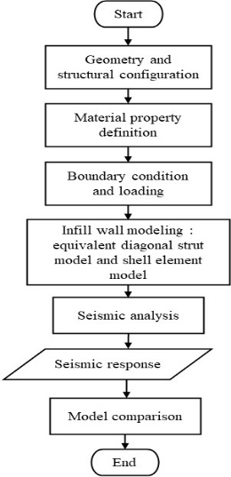
Figure 1 presents a schematic overview of the modeling workflow adopted in this study. The process begins with the definition of geometry and material properties, followed by the application of boundary conditions and seismic loading. Masonry infill frames were then modeled using two alternative approaches. Finally, seismic response parameters were extracted and compared to evaluate the performance and applicability of each modeling technique.
2.1. Frame Modeling
The building was designed as an eight-story office building located in Yogyakarta city with a height of 32 m. The building has dimensions of 0.5 m x 0.5 m column, and 0.5 m x 0.3 m beam, 0.12 m floor slab, and 0.1 m roof slab. The building structure is reinforced concrete, while the roof is a concrete slab. Other features of the building are as follows:
•Height of each floor : 4 m
•Building dimension : 16 m x 20 m
•Wall material : brick
•Thickness of wall : 15 cm
•Specific weight of brick : 22.72 kN/m3
•Brick quality (f’m) : 1.816 MPa
•Modulus of elasticity : k x f’m = 750 x 1.816 = 1362 MPa
•Poisson’s ratio : 0.15
•Concrete compressive strength (f’c) : 30 MPa
The material properties were based on research by Rindana22), while the building specification was based on SNI 1727:202023), SNI 2847:201924), and SNI 1726:201925) related to seismic and concrete design26).
Figure 2 represents the model that was made in three conditions: open frame, infilled frame with openings, and infilled frame.

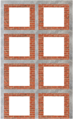
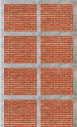
Three-dimensional structural models were developed using SAP2000 with two infill conditions: equivalent diagonal strut and shell element model. In the shell element model, the infilled frame was modeled as shell elements which assumed to behave as homogeneous materials and discretized into multiple finite elements (mesh areas). For the infilled frame with openings condition, the area was defined as 25% of the total wall area. For the equivalent diagonal strut approach, the masonry infill frame was represented by an equivalent diagonal compression strut based on a macro-modeling concept. The effective strut width represents the interaction between the infilled frame and the surrounding RC frame, as expressed in Eq.1 – 327). For an infilled frame with openings, the reduction in stiffness and strength due to the presence of openings is incorporated through a reduction factor28) (Eq.4) based on the opening area ratio.
2.2. Structural load
In this study, the building function was an office and
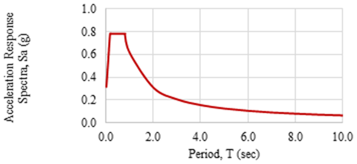
analyzed by seismic response spectrum located in Yogyakarta city with medium soil type (Figure 3). The structural loads were analyzed with a combination of loading by SNI 1726:2019 and then by pushover analysis. Pushover analysis is a method that evaluates the behaviour of a structure under static seismic lateral forces that increase in stages until it reaches the plastic limit. This analysis aims to determine the structure’s response to an earthquake based on the deformation that occurs29,30). Pushover analysis produces capacity curves that are useful for illustrating the relationship between base shear force, providing information on the strength of the structure.
2.3. Structure performance based on ATC-40
The seismic performance of a structure was determined by the capacity spectrum method based on ATC-40. This method includes a capacity curve and a demand response spectrum curve, displacement spectra (ADRS/ Acceleration-Displacement Response Spectra). Performance levels are expressed in terms of immediate occupancy, life safety, and collapse prevention, each of which indicates the ability of the structure to resist seismic lateral forces and protect its occupants.
3. Results and discussion
3.1. Reinforced concrete structure design
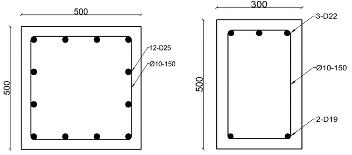
The reinforcement requirements required by the structure were determined by applying Concrete Frame Design based on SNI 2847:2019. The reinforcement requirements (Figure 4) used in the open frames were determined as a reference for the infilled frame with openings and the infilled frame in both wall models.
3.2. Load Combination Analysis
Based on analysis of the open frames, it was found that the combination of load: 1.356 dead load + live load + 0.3 force (x axis) + force (y axis) resulted in the most significant values of axial force, shear force, and bending moment compared to other loading combinations. Therefore, this load combination was used as a reference for subsequent analysis.
3.3. Lateral displacement behaviour
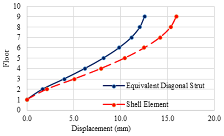
Table 1, Figure 5, and Figure 6 present the displacement for the infilled frame with openings and the fully infilled frame, analyzed using the equivalent diagonal strut and shell element modeling approaches. With the expected structural response of a multi-story frame under lateral loading. While for Y-direction can be seen at Table 2, Figure 7, and Figure 8. In all cases, the displacement increased progressively from the first floor to the roof floor.
Table 1: X-axis displacement (in mm)
| Infilled Frame with Openings | Infilled Frame | |||
|---|---|---|---|---|
| Floor | Equivalent Diagonal Strut | Shell Element Model | Equivalent Diagonal Strut | Shell Element Model |
| 1st Floor | 0.000 | 0.000 | 0.000 | 0.000 |
| 2nd Floor | 1.670 | 2.135 | 1.286 | 1.991 |
| 3rd Floor | 3.993 | 5.094 | 2.847 | 4.353 |
| 4th Floor | 6.183 | 7.908 | 4.301 | 6.544 |
| 5th Floor | 8.150 | 10.409 | 5.670 | 8.510 |
| 6th Floor | 9.820 | 12.524 | 6.857 | 10.188 |
| 7th Floor | 11.138 | 14.188 | 7.840 | 11.518 |
| 8th Floor | 12.047 | 15.329 | 8.562 | 12.444 |
| Roof | 12.545 | 15.938 | 9.009 | 12.948 |
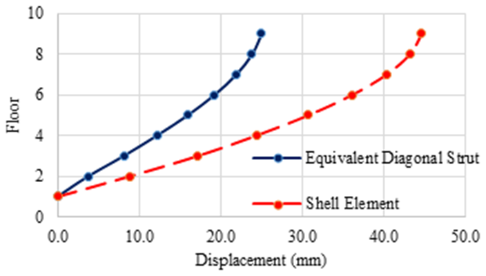
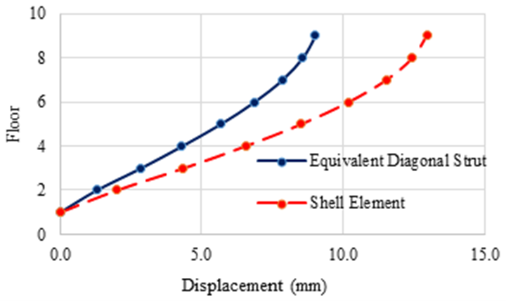
Table 2: Y-axis displacement (in mm)
| Infilled Frame with Openings | Infilled Frame | |||
|---|---|---|---|---|
| Floor | Equivalent Diagonal Strut | Shell Element Model | Equivalent Diagonal Strut | Shell Element Model |
| 1st Floor | 0.000 | 0.000 | 0.000 | 0.000 |
| 2nd Floor | 5.709 | 7.508 | 3.726 | 8.854 |
| 3rd Floor | 13.415 | 18.114 | 8.092 | 17.187 |
| 4th Floor | 20.594 | 28.208 | 12.137 | 24.372 |
| 5th Floor | 27.021 | 37.151 | 15.926 | 30.755 |
| 6th Floor | 32.448 | 44.670 | 19.193 | 36.144 |
| 7th Floor | 36.697 | 50.534 | 21.875 | 40.359 |
| 8th Floor | 39.578 | 54.492 | 23.821 | 43.224 |
| Roof | 41.096 | 56.536 | 24.985 | 44.701 |

A comparison between the two modeling approaches shows that the shell element model consistently predicts higher displacement than the equivalent diagonal strut model in both directions. This behavior is expected because the shell element model can capture local deformation patterns, in-plane shear deformation, cracking progression, and nonlinear interactions between the infill and the surrounding frame. In contrast, the equivalent diagonal strut model simplifies the infill as a single compressive element, leading to an overestimation of stiffness and an underestimation of lateral displacement.
In the X-axis direction, the maximum roof displacement for the infilled frame with openings was 15.938 mm in the shell element model and 12.545 mm in the equivalent diagonal strut model—an increase of approximately 27%. For the fully infilled frame, the shell element model produced a roof displacement of 12.948 mm, which is 44% higher than the 9.009 mm obtained from the equivalent diagonal strut model. Similarly, in the Y-axis direction, the infilled frame with openings exhibited a roof displacement of 56.536 mm using the shell element model, compared to 41.096 mm with the equivalent diagonal strut model, representing an increase of about 38%. For the fully infilled frame, the shell element model result (44.701 mm) was approximately 79% greater than that of the equivalent diagonal strut model (24.985 mm). These differences are consistent with the findings by Asteris31), who demonstrated that diagonal strut models tend to underestimate displacement demands, particularly in structures with strong frame-infill interaction.
The effect of openings in the infill wall was also significant in both directions. Frames with openings consistently exhibited higher displacements than fully infilled frames, indicating a reduction in overall stiffness and lateral load resistance. The openings interrupt the continuity of the infill, weakening its ability to transfer shear forces and increasing lateral flexibility. At the roof level, the infilled frame with openings (shell element) experienced approximately 23% higher displacement in the X-axis and 26% higher displacement in the Y-axis compared to the fully infilled frame modeled.
3.4. Inter-story deviation analysis
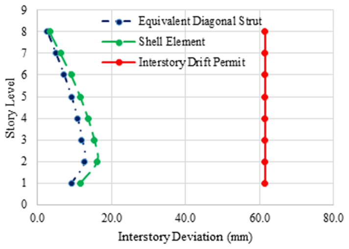
The X-axis and Y-axis inter-story deviation can be seen in Table 3 and 4, respectively. Inter-story deviation, representing the relative lateral displacement between consecutive floors, is a critical indicator of structural deformation capacity and potential damage under lateral loads. While, Figure 9 – 12 illustrates the inter-story deviation of the model, comparing the equivalent diagonal strut model (blue line) and the shell element model (green line). While the red line is for the inter-story permit (60 mm) based on SNI 1726:2019.
Table 3: X-axis inter-story deviation (in mm)
| Infilled Frame with Openings | Infilled Frame | |||
|---|---|---|---|---|
| Story | Equivalent Diagonal Strut | Shell Element Model | Equivalent Diagonal Strut | Shell Element Model |
| 1 | 9.185 | 11.742 | 7.072 | 10.949 |
| 2 | 12.777 | 16.277 | 8.584 | 12.991 |
| 3 | 12.046 | 15.473 | 8.002 | 12.055 |
| 4 | 10.819 | 13.757 | 7.526 | 10.812 |
| 5 | 9.184 | 11.633 | 6.531 | 9.225 |
| 6 | 7.250 | 9.153 | 5.405 | 7.320 |
| 7 | 4.998 | 6.275 | 3.973 | 5.089 |
| 8 | 2.739 | 3.347 | 2.457 | 2.772 |
Table 4: Y-axis inter-story deviation (in mm)
| Infilled Frame with Openings | Infilled Frame | |||
|---|---|---|---|---|
| Story | Equivalent Diagonal Strut | Shell Element Model | Equivalent Diagonal Strut | Shell Element Model |
| 1 | 31.398 | 41.293 | 20.494 | 48.697 |
| 2 | 42.384 | 58.333 | 24.011 | 45.831 |
| 3 | 39.485 | 55.519 | 22.248 | 39.515 |
| 4 | 35.347 | 49.185 | 20.839 | 35.111 |
| 5 | 29.850 | 41.354 | 17.968 | 29.636 |
| 6 | 23.368 | 32.252 | 14.753 | 23.185 |
| 7 | 15.850 | 21.770 | 10.700 | 15.756 |
| 8 | 8.347 | 11.240 | 6.402 | 8.123 |
Fig. 9: X-Axis Inter-story Deviation of Infilled Frame with Openings | Fig. 10: X-Axis Inter-story Deviation of Infilled Frame |
|---|---|
Fig. 11: Y-Axis Inter-story Deviation of Infilled Frame with Openings | Fig. 12: Y-Axis Inter-story Deviation of Infilled Frame |
For both directions, the maximum deviation generally occurs from the lowest to middle stories, particularly the second or third story, and gradually decreases toward the upper floors. This distribution shows that the expected behavior of multi-story frames is where shear forces and lateral demands are highest in the lower portions of the structure.
A clear distinction was observed between the two modeling approaches. The shell element model consistently predicts higher inter-story deviations than the equivalent diagonal strut model.
In the X-axis direction, the maximum second-story deviation for the infilled frame with openings was 16.277 mm (shell element model) and 12.777 mm (equivalent diagonal strut), an increase of approximately 27%. For the fully infilled frame, the shell element model resulted in 12.991 mm, about 51% greater than the 8.584 mm from the strut model.
In the Y-axis direction, the peak second-story deviation of the infilled frame with openings was 58.333 mm (shell element model) compared to 42.384 mm (equivalent diagonal strut), corresponding to an increase of 38%, while the fully infilled frame exhibited 45.381 mm (shell element model) and 24.011 mm for the equivalent diagonal strut, a nearly 91% increase. These differences highlight the greater flexibility captured by the shell element model, which accounts for local deformations and nonlinear frame-infill interactions, in contrast to the stiffer behavior predicted by the simplified strut model.
The presence of openings in the infill wall has an impact on inter-story deviation. For both X- and Y-axis responses, the infilled frame with openings exhibits consistently higher deviations than the fully infilled frame. At the second story, the X-axis deviation of the frame with openings is approximately 25% higher than that of the fully infilled frame, while the Y-axis deviation shows a similar increase of 27%. This increase is due to the reduction in effective stiffness and the interruption of load transfer through the infill, which amplifies lateral deformations, particularly in the lower and middle stories. The findings demonstrate that adding openings in infill panels reduced the deviation demands of low-period stiff structures32).
3.5. Capacity
The capacity of each model can be seen in Figure 13 – 16. Figure 13 and Figure 14 represent the capacity curve of an infilled frame with openings, while Figure 15 and Figure 16 represent the infilled one. Across all the models, the infilled frame resulted in higher base shear, especially for the shell element model.
The comparison of capacity curves indicates that shell element model consistently predicts higher base shear capacity than the equivalent diagonal strut model in both directions. Specifically, for the infilled frame with openings, the maximum base shear by shell element model was 9.722% higher in the X direction, and 7.369% higher in the Y direction. Similarly, for the fully infilled frame, using a shell element model produced a maximum base shear that was 7.926% higher in the X direction and 5.739% higher in the Y direction than the equivalent diagonal strut model.
These differences suggest that the shell element model captures the contribution of the infill more effectively, leading to a higher overall lateral load resistance in both directions. Although the shell element model exhibits lower initial stiffness, it captures distributed stress transfer and progressive cracking, allowing higher base shear capacity. In contrast, the equivalent diagonal strut model is stiffer in the elastic range but strength-limited by its simplified single strut representation, resulting in earlier strength limitation.
Despite these differences in base shear capacity, all models comply to the Strong Column–Weak Beam (SCWB) concept.
Fig. 13: X-Axis Capacity Curve of Infilled Frame with Openings | Fig. 14: Y-Axis Capacity Curve of Infilled Frame with Openings |
|---|---|
Fig. 15: X-Axis Capacity Curve of Infilled Frame | Fig. 16: Y-Axis Capacity Curve of Infilled Frame |
This is evidenced by the initial formation of plastic hinges in the beams, followed by the subsequent development of plastic hinges in the columns as the load increases, demonstrating that the columns remain stronger than the beams as intended in SCWB design principles.
However, the presence of an opening reduced the capacity of the infilled frame by about 30%, in agreement with the experimental findings of Dattatreya33) and Ubaid34)
3.6. Ductility Factor Analysis
The ductility factor was evaluated from the capacity curve as the ratio of the ultimate displacement to the yield displacement. Figure 17 illustrates the capacity curve of infilled frame with shell element model in the Y direction. Initial yielding occurred at a base shear of 6857 kN with corresponding displacement of 88.817 mm, while the maximum capacity was obtained at a base shear of 22615 kN and displacement of 387.956 mm.
The ductility factor results summarized in Table 5 and 6 show distinct differences between modeling approaches for infilled frames. For an infilled frame with openings, the shell element model exhibits higher ductility compared to the equivalent diagonal strut model in both directions. Specifically, the X-axis ductility increased from 5.385 to 5.687, and the Y-axis ductility increased from 4.597 to 5.344. This indicates that modeling the infill as a shell element model allows the frame to sustain larger deformations before failure, capturing the more flexible behavior of the infill-wall interaction.
In terms of ductility, the differences between the two modeling approaches are more pronounced. The shell element model shows a ductility factor of 4.108 in the X direction and 4.368 in the Y direction, whereas the equivalent diagonal strut model reaches only 2.209 and 1.726, respectively. These results suggest that the diagonal strut model tends to underpredict the deformability of the infilled frame, likely due to its simplified representation of the wall behavior3,35). In contrast, the shell element model more accurately reflects the distributed interaction between the frame and the infill, resulting in a higher capacity to accommodate inelastic deformations.
| Model | X-Axis | Y-Axis |
|---|---|---|
| Equivalent Diagonal Strut | 5.385 | 4.597 |
| Shell Element Model | 5.687 | 5.344 |
| Model | X-Axis | Y-Axis |
|---|---|---|
| Equivalent Diagonal Strut | 2.209 | 1.726 |
| Shell Element Model | 4.108 | 4.368 |
In general, these findings highlight the importance of selecting an appropriate modeling technique, as shell element model provide a more realistic prediction of ductility, particularly in scenarios where large lateral deformations are expected36,37). More accurate modeling, such as using shell elements, enables engineers to better predict real deformation demands, avoid over-conservative assumptions, and optimize material use. A design that accurately captures actual stiffness and ductility can prevent unnecessary over-strengthening, contributing to reduced material consumption. The improved ductility of the shell element model also implies better energy dissipation capacity during seismic events, enhancing the structural resilience of the frame.
3.7. Performance Level Analysis
Determining performance points requires several parameters calculated based on ATC-4038), such as determining the structural behavior type, and a damping value of 5%. Structural Behavior Type was determined as type B, meaning that the building is a new one with a long-period response39). The maximum total deviation was the displacement value at the performance point divided by the building height, and then compared with the deviation limit at the structural performance level based on ATC-40.
The results of performance level analysis can be seen in Table 7 and 8. In an infilled frame with openings, the equivalent diagonal strut model has the performance level of Immediate Occupancy (IO). Meanwhile, the shell element model has a Damage Control (DC) performance level. In the infilled frame, both models have IO performance levels. From design perspective, an IO performance level implies minimal structural damage and continued post-earthquake functionality, whereas a DC performance level allows for controlled damage, such as cracking of infill walls and inelastic behavior, while maintaining stability and life safety.
| Model | X-Axis | Y-Axis | ||
|---|---|---|---|---|
| Maximum Total Deviation | Performance Level | Maximum Total Deviation | Performance Level | |
| Equivalent Diagonal Strut | 0.00975 | IO | 0.00928 | IO |
| Shell Element Model | 0.01147 | DC | 0.01125 | DC |
| Model | X-Axis | Y-Axis | ||
|---|---|---|---|---|
| Maximum Total Deviation | Performance Level | Maximum Total Deviation | Performance Level | |
| Equivalent Diagonal Strut | 0.00569 | IO | 0.00506 | IO |
| Shell Element Model | 0.00947 | IO | 0.00916 | IO |
4. Conclusion
The comparative analysis of masonry wall modeling using the equivalent diagonal strut and shell element model provides valuable insight into their influence on the seismic performance of reinforced concrete (RC) frame structures. The results from the displacement value analysis show that modeling the infill wall as an equivalent diagonal strut significantly increases the overall stiffness of the structure. This higher stiffness leads to smaller lateral displacements compared to models using shell element model, which represent the masonry wall in greater geometric and material detail. Although the diagonal strut model effectively captures the global stiffness contribution of the infill, it simplifies the complex interaction between the frame and the masonry panel, resulting in a stiffer and less deformable structural response.
Similarly, the inter-story deviation analysis confirms that the equivalent diagonal struts model exhibits smaller deviation values than those modeled with shell element model. This outcome shows the influence of increased stiffness provided by the diagonal strut representation, which restricts lateral deformation under seismic loads. In contrast, the shell element model allows for a more realistic distribution of stresses and strains, leading to larger but more accurate deviation predictions that better represent actual structural behaviour during earthquakes.
The ductility factor analysis further emphasizes the limitations of the simplified diagonal strut approach. The shell element model demonstrates a higher ductility factor, indicating that structures modeled with this approach possess greater deformation capacity and energy dissipation ability before failure. This is because the shell element model formulation can simulate progressive cracking and nonlinear stress redistribution within the masonry wall, which are not captured by the simplified strut representation. As a result, the shell element model offers a more comprehensive understanding of the structure’s post-yield behavior and overall seismic resilience.
The performance level analysis also highlights clear differences between the two modeling approaches. For infilled frames with openings, the equivalent diagonal strut model corresponds to an Immediate Occupancy (IO) performance level, suggesting limited damage and minimal deformation under design-level seismic excitation. On the other hand, the shell element model reaches a Damage Control (DC) performance level, which, although indicating greater deformation, more accurately represents the realistic response of the structure with openings. For fully infilled frames without openings, both modeling approaches achieve the Immediate Occupancy level, confirming the beneficial effect of masonry infills in enhancing seismic performance.
Nomenclature
| Symbol | Description (Unit) |
|---|---|
| the opening area ratio | |
| the modulus of elasticity of the RC frame | |
| the modulus of elasticity of the masonry | |
| height of the column between beam centerlines | |
| the moment of inertia of the column section | |
| the infill frame length | |
| the diagonal length of the infill wall | |
| the wall thicknesses | |
| the angle formed between the infill wall height and length | |
| a coefficient used to determine the effective strut width |
References
- V. Sarhosis, and J. V. Lemos, “A detailed micro-modelling approach for the structural analysis of masonry assemblages,” Comput. Struct., 206, 66–81 (2018). doi:10.1016/j.compstruc.2018.06.003.
- A. Kumar, and K. Pallav, “Experimental and numerical investigation of old masonry wall using a macro-modeling approach,” The Open Civil Engineering Journal, 14 (1), 334–349 (2020). doi:10.2174/1874149502014010334.
- I.R. Hapsari, S.A. Kristiawan, S. Sangadji, and B.S. Gan, “Damage states investigation of infilled frame structure based on meso modeling approach,” Buildings, 13 (2) (2023). doi:10.3390/buildings13020298.
- C.A. Filippou, N.C. Kyriakides, and C.Z. Chrysostomou, “Numerical modeling of masonry-infilled rc frame,” The Open Construction & Building Technology Journal, 13 (1), 135–148 (2019). doi:10.2174/1874836801913010135.
- M. El-Diasity, S. Salah, M.O.R. El-Hariri, A.A. Gamal, and T.S. Elsalakawy, “Numerical and experimental behavior of two-story confined masonry structure subjected to cyclic loads,” Int. J. Concr. Struct. Mater., 17 (1) (2023). doi:10.1186/s40069-023-00632-1.
- S. Kömürcü, and A. Gedikli, “Macro and micro modeling of the unreinforced masonry shear walls,” Turkey) EJENS, 3 (2), 116–123 (2019).
- D. Decret, Y. Malecot, Y. Sieffert, F. Vieux-Champagne, and L. Daudeville, “A new macro-element for predicting the behavior of masonry structures under in-plane cyclic loading,” Buildings, 768 (14) (2024). doi:10.3390/buildings14030768.
- H. Pirsaheb, M. Javad Moradi, and G. Milani, “A multi-pier mp procedure for the non-linear analysis of in-plane loaded masonry walls,” Eng. Struct., 212 (2020). doi:10.1016/j.engstruct.2020.110534.
- M.A. Bouarroudj, and Z. Boudaoud, “Comparison between numerical modeling approaches of infilled frames under in-plane load,” Front. Built Environ., 7 (2022). doi:10.3389/fbuil.2021.783051.
- J. Srechai, S. Leelataviwat, W. Wararuksajja, and S. Limkatanyu, “Multi-strut and empirical formula-based macro modeling for masonry infilled rc frames,” Eng. Struct., 266 (2022). doi:10.1016/j.engstruct.2022.114559.
- F. Yáñez, M. Astroza, A. Holmberg, and O. Ogaz, “Behavior of Confined Masonry Shear Walls with Large Openings,” in: 13th World Conference on Earthquake Engineering, Vancouver, B.C., Canada, 2004.
- H.A. Awla, M. Karaton, N.R. Taher, N. Hamah Sor, and M.M. Arbili, “Evaluation of the accuracy of shell elements when used for modelling masonry minaret structures under seismic loading,” Asian Journal of Civil Engineering, 24 (7), 2011–2018 (2023). doi:10.1007/s42107-023-00620-6.
- H.A. Awla, and M.M. Arbili, “Accuracy Assessment of Shell Finite Elements for Considering to Masonry Structures Under Seismic Loading,” in: Geotechnical Engineering and Sustainable Construction - Sustainable Geotechnical Engineering, Springer, 2022: pp. 557–568. doi:10.1007/978-981-16-6277-5_45.
- A. Hamid, Suranto, D.C. Istiyanto, R.C. Yuniardi, S.A. Aziiz, Y.T.D. Harita, A.B. Widagdo, S.A. Latief, I. Wulandari, and R. Firmansyah, “Structural performance of parallel concrete panel container towards green coastal and port’s retaining wall: a comparison of tie rod configurations,” EVERGREEN Joint Journal of Novel Carbon Resource Sciences & Green Asia Strategy, 11(3), 2783–2790 (2024). doi:10.5109/7236917.
- P.R. Prakash, M. Azenha, J.M. Pereira, and P.B. Lourenço, “Finite element based micro modelling of masonry walls subjected to fire exposure: framework validation and structural implications,” Eng. Struct., 213 (2020). doi:10.1016/j.engstruct.2020.110545.
- A. Kumar, A.K. Chanda, and S. Angra, “Numerical modelling of a composite sandwich structure having non metallic honeycomb core,” EVERGREEN Joint Journal of Novel Carbon Resource Sciences & Green Asia Strategy, 8 (4), 759–767 (2021). doi:10.5109/4742119.
- S. Nayak, and M. Prasanna Kumar, “Mechanical characterization and static analysis of natural fiber based composite propeller blade,” EVERGREEN Joint Journal of Novel Carbon Resource Sciences & Green Asia Strategy, 10(2), 805–812 (2023). doi:10.5109/6792832.
- A. Kosim, S. N. Taufiq, A. P. Rezky, M. U. Nur, N. Afid, R. N. Rezky, A. Riki, H. Ryan, S. A. Rian, and A. W. Fajar, “Experimental study of adhesively bonded single lap joint behaviour in cfrp-to-cfrp, al-to-al, and cfrp-to-al configurations,” EVERGREEN Joint Journal of Novel Carbon Resource Sciences & Green Asia Strategy, 12 (3), 1531–1544 (2025). doi:10.5109/7388847.
- I.J. Maknun, and A. Yvas, “Effect of mesh orientation on accurate solution in static analysis of composite plates structures,” EVERGREEN Joint Journal of Novel Carbon Resource Sciences & Green Asia Strategy, 11(4), 3325–3332 (2024). doi:10.5109/7326967.
- H. García, J. Jiménez-Pacheco, and J. Ulloa, “Effective properties of masonry structures and macro-model analysis with experimental verification,” Results in Engineering, 23 (2024). doi:10.1016/j.rineng.2024.102546.
- A. Ahmed, K. Shahzada, S.M. Ali, A.N. Khan, and S.A.A. Shah, “Confined and unreinforced masonry structures in seismic areas: validation of macro models and cost analysis,” Eng. Struct., 199 (2019). doi:10.1016/j.engstruct.2019.109612.
- R. Rindana, and M. Teguh, “Characteristics of Masonry Wall with Locally Produced Brick Quality (Special Region Yogyakarta) (In Indonesia),” 2017. https://dspace.uii.ac.id/handle/123456789/5289 (accessed February 3, 2026).
- “SNI 1727-2020 Minimum Design Loads and Related Criteria for Buildings and Other Structures (in Indonesia),” Minimum Design Loads and Related Criteria for Buildings and Other Structures, 2020.
- “SNI 2847-2019 Structural Concrete Requirements for Building Structures and Explanations (in Indonesia),” National Standardization Agency, 2019.
- “SNI 1726-2019 Earthquake Resistance Planning Procedures for Buildings and Non-Building Structures (in Indonesia),” National Standardization Agency, 2019.
- H. Nurjaman, S. Suwito, D. Dinariana, G. Suprapto, B. Budiono, and M. Fau, “Development of numerical model of a high performance precast concrete system equipped with base isolation,” EVERGREEN Joint Journal of Novel Carbon Resource Sciences & Green Asia Strategy, 9 (2), 547–555 (2022). doi:10.5109/4794186.
- P.G. Asteris, S.T. Antoniou, D.S. Sophianopoulos, and C.Z. Chrysostomou, “Mathematical macromodeling of infilled frames: state of the art,” Journal of Structural Engineering, 137 (12), 1508–1517 (2011). doi:10.1061/(asce)st.1943-541x.0000384.
- P.G. Asteris, I.P. Giannopoulos, and C.Z. Chrysostomou, “Modeling of infilled frames with openings,” The Open Construction and Building Technology Journal, 6, 81–91 (2012). doi:10.2174/1874836801206010081.
- J. Vemuri, S. Ehteshamuddin, M. Ravula, and S. Kolluru, “Pushover analysis of soft brick unreinforced masonry walls using analytical and numerical approaches,” in: Mater. Today Proc., Elsevier Ltd, 2019: pp. 420–425. doi:10.1016/j.matpr.2019.10.025.
- A. Sharma, and R. Khare, “Pushover analysis for seismic evaluation of masonry wall,” International Journal of Structural and Civil Engineering Research, (2016). doi:10.18178/ijscer.5.3.235-240.
- P.G. Asteris, and D.M. Cotsovos, “Numerical investigation of the effect of infill walls on the structural response of rc frames,” The Open Construction and Building Technology Journal, 6, 164–181 (2012). doi:10.2174/1874836801206010164.
- A. Etemadi, and C. Balkaya, “The role of masonry infills on the interstory drift demand of reinforced concrete frames,” Soil Dynamics and Earthquake Engineering, 180 (2024). doi:10.1016/j.soildyn.2024.108599.
- D. Tripathy, and V. Singhal, “Experimental and analytical investigation of opening effects on the in-plane capacity of unreinforced masonry wall,” Eng. Struct., 311 (2024). doi:10.1016/j.engstruct.2024.118161.
- U.A. Mughal, A.U. Qazi, A. Ahmed, U.U. Sahar, and M.M. Ajmal, “Comparative analysis of mechanical characteristics in masonry walls: impact of aspect ratios and opening percentages,” European Journal of Environmental and Civil Engineering, 28 (15), 3639–3660 (2024). doi:10.1080/19648189.2024.2356018.
- Z. Chai, Z. Guo, X. Liu, and Y. Jiang, “Comparative study on diagonal strut model of infill wall,” SDHM Structural Durability and Health Monitoring, 12 (3), 169–187 (2018). doi:10.3970/sdhm.2018.00240.
- P. Sultana, and M.A. Youssef, “Seismic performance of steel moment resisting frames utilizing superelastic shape memory alloys,” J. Constr. Steel Res., 125, 239–251 (2016). doi:10.1016/j.jcsr.2016.06.019.
- I.M. Saad, H.A. Mohamed, M. Emara, A. El-Zohairy, and S. El-Beshlawy, “Finite element modeling and analysis of rc shear walls with cutting-out openings,” Modelling, 5 (3), 1314–1338 (2024). doi:10.3390/modelling5030068.
- “Improvement of Nonlinear Static Seismic Analysis Procedures FEMA 440,” 2005.
- D. Morris, “Effects of outrigger & belt truss system on high-rise building structure performance,” in: IOP Conf. Ser. Mater. Sci. Eng., IOP Publishing Ltd, 2020. doi:10.1088/1757-899X/1007/1/012189.