
Abstract
To strengthen frame structures against earthquake forces, lateral stiffeners are essential. The Eccentrically Braced Frame (EBF) system increases stiffness and provides good ductility through horizontal link beams. Ground Granulated Blast-Furnace Slag (GGBFS) improves concrete’s mechanical properties by reducing porosity due to its finer particles compared to ordinary Portland cement (OPC). This study investigates the lateral behavior and capacity of EBF braced frames with horizontal link beams, focusing on closer spacing of transverse reinforcement combined with GGBFS. Results show that while concentrically braced frames (CBF) have the highest load-carrying capacity, EBF-V-15 specimens demonstrate superior cyclic behavior, ductility, and stiffness.
Keywords: Cyclic Load, Ductility, EBF, GGBFS, Horizontal Link Beam
Outline
1. Introduction
A unique technique are needed to increase the lateral stability of the structure to make it stiffer and ductile, making it more vulnerable to wind and seismic pressure1). According to2) concrete structures are reinforced so that when they are subjected to seismic loads, the primary components can function as a single unit and perform at their best. For example, several reliable structural engineering sources emphasize that proper bracing arrangements in braced frames improve stiffness and decrease internal forces, especially flexural moments, in columns and beams3). This supports the contention that bracing improves strength by increasing frame strength and lateral stiffness through the installation of diagonal members4).
A form of bracing system known as eccentrically braced frame (EBF) combines the rigidity of concentrically braced frame (CBF) with the ductility of moment resisting frame (MRF)5) According to6) EBFs are often used as seismic lateral load resisting systems and are known for their ability to behave well during strong earthquakes. The frame has excellent ductility and performs well in terms of stiffness. The links experience inelastic deformations in an intense seismic event, and they end up serving as the main source of energy dissipation7). Previous studies have compared the strengths of EBF structures with different configurations. The strongest option, according to the results, is the EBF with V-shaped bracing. Other advantages include faster post-earthquake maintenance, minimal modification of the current structure, and improved performance of the mainframe system, which is supported by connecting beams8,9). However, Type V EBF bracing also offers architectural advantages because it has openings that can be used to place doors and windows10). However, the performance of the EBF is significantly affected by the length of the link, which is an important component of the EBF system. In terms of frame stiffness and ductility, the links must be limited so that they are neither too short nor too long7). In addition, the study by11), emphasizes that energy is dissipated in EBF by shear or bending deformation of the links, highlights the importance of connection strength in EBFs with V-type stiffeners. Beam location also affects structural response. A horizontal position (at the center) will benefit the lateral capacity more than a vertical connection beam, allowing greater stiffness and maximum load while retaining ductility12).
Steel components are often used to reinforce structures because of their toughness and strength13). Since steel and concrete have very different moduli of elasticity and strength, however, the main concern when using steel reinforcing elements to reinforce concrete structures is the premature collapse of the original concrete structural member connected to the reinforcing elements14). Conversely, steel necessitates additional measures to prevent rust, one such measure being the addition of zinc. It is imperative to acknowledge that this will have an impact on the overall construction costs15). This issue is particularly important with regard to seismic performance, as mismatched material qualities can affect the overall stiffness and strength of the structure16). In general, reinforced concrete (RC) braced frames offer greater lateral stiffness, lower production costs, and a wider range of applications than steel braced frames. Seven reinforced concrete (RC) frames were studied and tested using reverse and vertical cyclic loading. They primarily investigated the hysteresis loops, strength, stiffness degradation, and failure modes of the RC braced frames. Their findings show that the braced frames significantly increase the energy dissipation while improving the lateral resistance and stiffness11). Similar findings were demonstrated by Setyowulan, who found that the use of reinforced concrete bracing improves the performance of the frame by increasing its capacity and ductility17). In particular, research has been conducted on concrete and EBF bracing. It is found that the ductility of the Structure is directly influenced by the link beam element length, with a longer link beam providing better results. Although the stiffness value is greatly reduced, the size of the link element influences the high ductility of the structure18). Consequently, it is believed that changing the transverse reinforcement will increase stiffness while maintaining the frame's ductility and lateral capacity.
Ming Narto's investigations indicates that specimens with 75 mm of transverse reinforcement are stiffer, although there is very little deformation. High deformation values can be obtained with 150 mm specimens19). However, in addition to the improvement of concrete's mechanical properties, there are other factors to consider. Low-carbon footprint materials are a must for greener buildings.
Currently, there are limitations in the availability of the materials used to make concrete, namely cement and sand. For this reason, alternative materials with similar properties are needed20). Conversely, Portland cement has emerged as a focal point in the broader effort to mitigate climate change, given its substantial contribution to carbon dioxide emissions during its production process21).
Concrete, as a manufactured material used in the construction industry, accounts for around 7-8% of global CO2 emissions from cement production22). Driving this is the significant demand for cement and concrete, which exceeds 4 billion tons globally each year23). Furthermore, the use of concrete has a significant impact on the environment due to the CO2 emitted in the manufacturing of cement and the consumption of natural aggregates24). As a result, it exacerbates several problems related to depleting natural resources and increasing global GHG emissions. It is therefore crucial to find substitutes for cement with a smaller carbon footprint to help produce more sustainable cement25). Thus, using renewable materials is the solution needed to create environmentally friendly and efficient buildings. Slag is one such material that can be used in concrete mixtures. In addition to reducing cement usage, it also helps reduce concrete production costs26). Lately, there has been much interest in using GGBFS instead of some OPC or other pozzolans. GGBFS, a byproduct of iron processing, possesses inherent economic value and can be utilized in a highly effective and beneficial manner27). GGBFS has been extensively studied and applied to concrete products in place of cement28). This is because it has a composition similar to cement and is pozzolanic, making it a useful cementitious constituent for cement/concrete composites29). Because of its compositional similarity to ordinary Portland cement or other pozzolanic materials, GGBFS has recently been used extensively in several countries. The use of GGBFS in concrete has several advantages: It is a more environmentally friendly material, it improves the appearance of the concrete, it extends the curing time of the concrete, and it increases the resistance to sulfate attack30). In addition, research has shown that GGBFS can improve concrete mix properties, with nano silica giving improved properties to concrete containing GGBFS31). Shariq's study on the effect of GGBFS on the concrete properties confirms the findings that GGBFS in concrete mixes increases the compression test value and that the addition of 20% GGBFS significantly increases the compression strength of 56-day concrete32). Similar results have been obtained in other studies on the effectiveness of GGBS on the performance of concrete, with the optimum replacement level being 20% GGBS, which improves the performance of concrete33). This is because GGBS has lower specific gravity than OPC, which improves overall concrete properties by supporting denser structure and reducing porosity34).
This enhances the resistance of the frame. There is a correlation between cracking pattern and width and the increase in load bearing capacity. As a structure is subjected to greater loads, it becomes more susceptible to cracking at yield. Therefore, this affects the increase in ductility of structures35). Similarly36), shows the increase of the failure mechanism in structures with a higher ductility. Moreover, minor cracks dominate the frame with diagonal shear classification37). In addition, on both sides of the column connection beam, the cracking observed tends to be symmetrical38,39).
This study investigates both mechanical and behavioral aspects of reinforced concrete bracing structures during cyclic loading. These included the use of GGBFS as a green material in the eccentric brace frame (EBF) and the adjustment of the spacing of the transverse reinforcement in the horizontal connection beams to improve stiffness and ductility as part of the sustainable energy concept.
2. Experimental Setup
Three models of braces were used in this experimental study: a control CBF, two V-type EBFs with 15 and 25 cm beam lengths, and two V-type EBFs with 15 and 25 cm beam lengths. Reinforced concrete is the main material for the frame and bracing, and the concrete quality used to be K-300 (24.9 MPa) with 20% GGBFS added. The frame dimensions are 80 x 110 cm.
A 150 mm stirrup spacing is used for columns and beams, while a 75 mm is used for link beams. A 6 mm and a 4 mm diameter is used for the longitudinal and transverse reinforcement of the beam structure. On the scale model, the element structures have dimensions of 100 mm x 100 mm with 20 mm concrete covering.
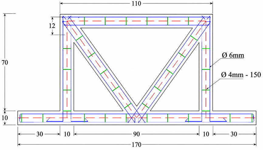
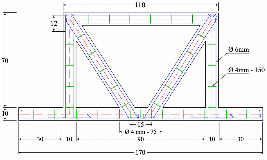
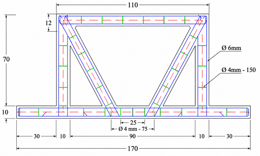
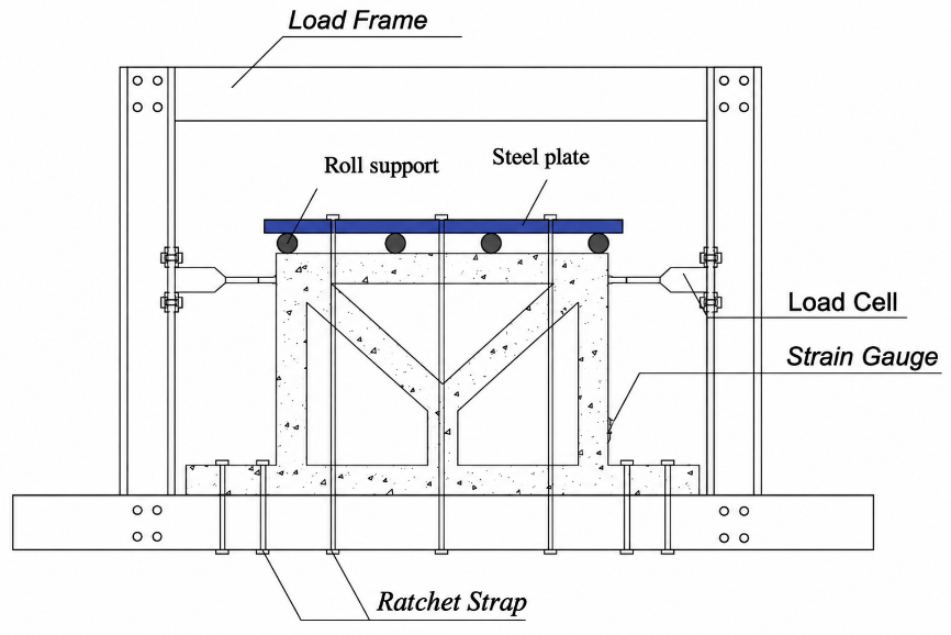
Table 1: Frames’s cyclic load scheme
| Phase | Load (kg) | Times push-pull cycle |
|---|---|---|
| 1 | 25% Ultimate Load = 1313 | 5 |
| 2 | 50% Ultimate Load = 2625 | 5 |
| 3 | 75% Ultimate Load = 3937,5 | 5 |
| 4 | 100% Ultimate Load = 5250 | 5 |
Details of the CBF and EBF-V cross-sections are given in Figure 1.
In this study, a mechanical vibrator was used to perfectly compact and mold the concrete, minimize pores, and ensure a consistent mixture40). Next, the specimens were covered with wet rug to ensure proper curing. This maximized the stability of the specimens' water content and moisture so that optimal concrete hydration could be achieved41).
The frame placement plan is shown in Figure 2, with one model positioned on the top of the loading frame. Rollers and steel plates were identified above the specimen and then clamped to provide a rolling mechanism (avoiding vertical displacement) so that the experiment focused on lateral displacement only. Two load cells were placed directly at the joints of the frame columns to provide a cyclic loading mechanism (tension and compression). Then, to see the amount of displacement, LVDTs were placed on both sides of the frame parallel to the load cell placement.
The maximum lateral load (P Max) that was applied to the frame was 5250 kg, according to the results of previous tests12). As shown in Table 1, The cyclic load scheme used for the frame is divided into four phases with five cycles each, based on the maximum load.
3. Result & Discussions
3.1. Load-displacement curve
First, the mechanical properties of the frame material, specifically concrete, were tested. The Compression test values for CBF, EBFV-15, and EBFV-25 were 27,84 MPa, 28,45 MPa, and 26,32 MPa, respectively, using five cylindrical concrete samples for each frame type. As a result, the concrete mix for the three types of frames has a compressive strength almost equal to or greater than the compressive strength of the design concrete.
The application of an effective curing method is paramount to ensure the attainment of compressive strength values that align with the desired quality and uniformity standards41). In this way, it can be said that the uniformity of the concrete quality in each of the specimens has been well implemented. These results are due to the implementation method and the high-quality control of the mixture. Additionally, using vibrators in the molding process and selecting the appropriate curing method positively impact quality consistency40,41).
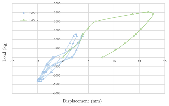
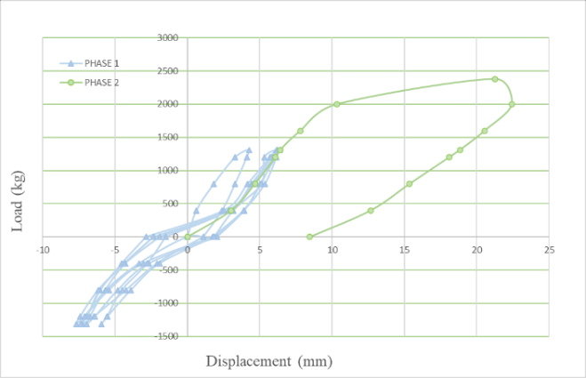
Through the cyclic loading test results, there are six data from three types of frames where each frame consists of 2 test specimens. All specimens were loaded to failure, which is characterized by cracks, damage, and large displacements in the frame structure. The data is the result of comparing load to displacement in each phase and cycle, which is then interpreted into a hysteresis curve (Figure 3 through Figure 5). Each specimen will have a different lateral behavior, mainly due to the maximum load and displacement magnitude.
All specimens were only able to reach half a cycle at peak load. The CBF specimen reached phase 3 of cycle 1 for compression loading and obtained a maximum load of 3370 kg and a displacement of 25,8 mm as shown in Figure 3.
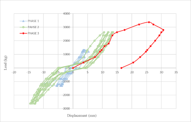
However, the CBF could only reach the second phase of cycle 5 for tensile loading with a full load of 2625 kg and a displacement of 14.47 mm. It can be observed that the increase in load is directly proportional to the displacement. A large load will also have a large displacement, resulting in a sloped curve with a wider area. In comparison to the eccentric strut, the CBF offers the greatest load capacity, but with a limited ductility ratio. Therefore, the CBF structure has a brittle behavior or the lowest ductility value among the other specimens. Based on previous research, it can be seen that there is a decrease in the capacity of CBF specimens by 3 - 35%18). A study using OPC as the main binding material obtained similar results, achieving a maximum load of 3,937.5 kg. Nevertheless, a decrease in displacement value of 1.8 mm was recorded in comparison to the displacement value of concrete using GGBFS.
This phenomenon can be attributed to the presence of GGBFS, which has been observed to reduce compressive strength but increase displacement values when replacing OPC at a certain percentage34).
The curve of specimen EBF-V-15 shows a larger area, indicating better ductility behavior when compared to CBF. Figure 4. The maximum shear load and deformation in the EBF-V-15 specimen were 2518 kg and 16.75 mm. Meanwhile, in the tensile state, the frame can only survive until phase 1 of cycle five or at a maximum load of 1313 kg with a displacement of 4.09 mm. The frame failed in phase 2 of the first cycle due to the push load. Visually, the EBF-V-15 specimen curve has a large area with a good slope, indicating that this specimen has ductile behavior. In addition, the yield and ultimate points can still be observed. When compared to previous research, there is similar behavior with CBF specimens, where there is a decrease in the frame capacity of EBF-V-15 specimens by 875 Kg18).
EBF-V-25 behaved similarly to EBF-V-15, where the frame collapsed in phase 2 of the first cycle at 2381 kg ultimate load and produced a displacement of 21.28 mm under thrust loading (Figure 5). The tensile condition showed similar results, where the frame survived until the 1st phase of the 5th cycle, at1313 kg ultimate load and producing 7.67 mm displacement. There was a decrease in the frame's strength of 137 kg when compared to the EBF-V-15 specimen due to the increased eccentricity of the frame. Conversely, the ductility value of EBF-V-25 has better results due to the longer link beam, resulting in greater deformation. However, previous research has shown there was a decrease in thrust load capacity of 31.35% in EBF-V-25 specimens18). Overall, CBF exhibited a linear elastic curve when analyzed. This illustrates that CBF specimens have a greater load capacity but the least deformation, resulting in brittle collapse.
3.2. Ductility of frames
Ductility is the ratio between ultimate displacement (Δu) to the yield displacement (Δy). The increase in cycles will produce a sloping curve. The ultimate displacement (Δu) is the displacement under load conditions reaching the maximum load (Pmax), while the yield displacement (Δy) is the displacement at 75% Pmax42), which can be seen more clearly in Figure 6.
Theoretically, the ductility will increase as the eccentricity of the frame increases. This is evidenced by the greater ductility of EBF as compared to CBF specimens. Table 2 shows that the EBF provides ductility results of 1.980 and 1.673 for eccentricity distances of 15 cm and 25 cm, respectively. Meanwhile, the CBF specimen is only able to produce a ductility value of 1.197. It can be seen that EBF-V-25 contradicts the existing theory where there is a decrease in ductility when compared to EBF-V-15 which is 1.689. This can be attributed to the large restraining effect on the tighter transverse reinforcement that limits the lateral deformation of EBF-V-25 specimen.
In particular, GGBFS increased the deformation capacity of the frame, when compared to the previous study using ordinary Portland cement (OPC), there was an increase in the average deformation for the three types of specimens CBF, EBFV-15, and EBFV-25 by 13.465 mm, 7.743 mm, and 14.878 mm, respectively. The improvement in the deformation performance of the frame ultimately resulted in an increase in the ductility ratio by 4.762%, 35.354%, and 10.341%18).
This assertion is further substantiated by the findings of other studies, which demonstrate the efficacy of utilizing GGBFS as a partial substitute for OPC, resulting in an augmentation in deformation of 8.86%43).
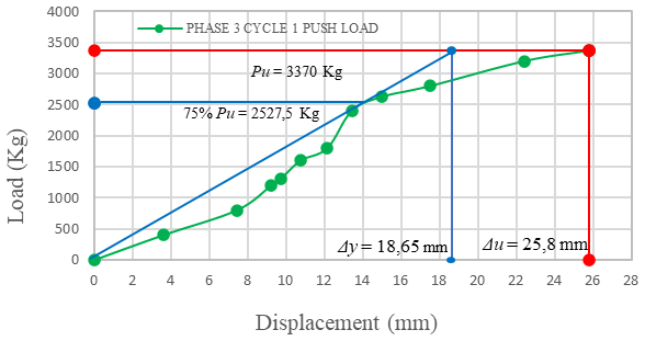
Table 2: Push Load Ductility Calculation
| Specimens | Eccentric (cm) | P Yield (Py) (kg) | P Ultimate (Pu) (kg) | Δu (mm) | Δy (mm) | Ductility Ratio (Δy /Δy) (kg/mm) | Average Ductility Ratio (Δy /Δy) (kg/mm) |
|---|---|---|---|---|---|---|---|
| A.1 | 0 | 1968,75 | 2625 | 21,33 | 21,10 | 1,011 | 1,197 |
| A.2 | 0 | 2527,50 | 3370 | 25,80 | 18,65 | 1,383 | |
| B.1 | 15 | 1888,50 | 2518 | 16,75 | 7,65 | 2,190 | 1,980 |
| B.2 | 15 | 1968,75 | 2625 | 15,31 | 8,65 | 1,770 | |
| C.1 | 25 | 1921,50 | 2562 | 21,06 | 13,72 | 1,535 | 1,689 |
| C.2 | 25 | 1785,75 | 2381 | 21,28 | 11,55 | 1,842 |
Table 3: Stiffness ratio of specimens
| Specimens | P Ultimate Push (Pu) (kg) | P Ultimate Pull (Pu) (kg) | Δu Push (mm) | Δu Pull (mm) | K (ΣPu/ΣΔu) (kg/mm) | Average Stiffness Ratio (kg/mm) |
|---|---|---|---|---|---|---|
| A.1 | 2625 | 2625 | 21,33 | 20,14 | 126,60 | 137,734 |
| A.2 | 3370 | 2625 | 25,80 | 14,47 | 148,87 | |
| B.1 | 2518 | 1313 | 16,75 | 5,03 | 175,90 | 169,433 |
| B.2 | 2625 | 2400 | 15,31 | 15,52 | 162,99 | |
| C.1 | 2562 | 1313 | 21,06 | 5,57 | 145,51 | 136,556 |
| C.2 | 2381 | 1313 | 21,28 | 7,67 | 127,60 |
This suggests the role of GGBS in modifying the collapse behavior of the frame to increase ductility.
3.3. Stiffness of frames
Frame's Stiffness is greatly affected by beam length. Conceptually, the CBF specimen has the greatest stiffness since the lateral load is transmitted as a pure compression-tension mechanism directly to the strut. However, experimentally, the EBFV-15 specimen is stiffer than the CBF, with a value of 1.980, which is only 1.197. This is attributed to the greater restraint provided by the denser transverse reinforcement (75 mm) in the horizontal link beam. In contrast, EBF-V-25 shows a different behavior where there is a decrease in stiffness due to the longer link beam. As the length of the link member increases, the damage will shift from shear to bending, so it is not recommended to use a close spacing of transverse reinforcement in the link member19). Table 3 provides the stiffness ratio of the three types of specimens.
3.4. Crack Pattern of frames
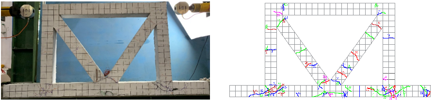
Once the concrete has attained its maximum strength and its capacity is exceeded, cracks begin to form and spread evenly along the surface44) . The crack pattern can be used to determine the behavior of the frame. Figure 7 to Figure 9 show a difference in the crack pattern between concentric braces and eccentric braces. The CBF specimen shows more cracks because the brace withstood a larger loading phase. The first crack occurred in Phase 1 of Cycle 1, when a thrust load of 800 kg was applied. This crack was categorized as flexural because it occurred diagonally, with the crack direction perpendicular to the brace axis. A total of 50 cracks occurred during the loading phase 3 cycle 1 under ultimate conditions, with a load of 3,370 kg. This represents an increase from 30 to 50 cracks compared to previous studies19). Fine cracks were evenly distributed on both sides of the frame at the joints of the lower columns and beams39). The cracks in the perpendicular direction of the brace element indicate that the CBF experienced flexural collapse. In this way, GGBFS has a positive impact on the development of frame ductility38).
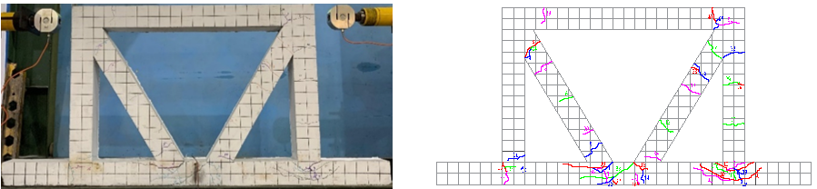
A link beam is a structural element that is engineered to experience early failure, thereby ensuring that any cracks that form will be concentrated in this element12). From a visual perspective, the categories of crack that have been identified in the bracing elements are flexural cracks and shear cracks in the link beams. The specimen was subjected to a maximum load of 2518 kg during the second cycle, resulting in a total of 56 cracks. This load level was identified as the ultimate condition of the specimen. The findings of the EBF-V-15 test exhibited analogous behavior to that observed in preceding studies, wherein impairment was evident in the link beam elements with prevalent shear cracks. GGBFS has been demonstrated to exert a beneficial effect, evidenced by an augmentation in the number of cracks by 12 when compared to frames utilizing OPC19).
A similar behavior was observed in this specimen as in the two previous specimens, CBF and EBF-V-15, where the first crack appeared at a thrust load of 800 kg. The EBF-V-25 reached its ultimate condition during the loading
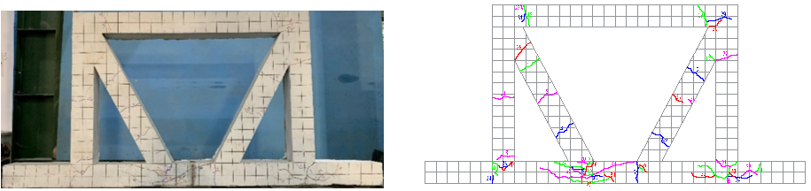
phase 2 cycle 1, with a load of 2,381 kg. The length of the link beam element exerted a significant positive influence on ductility, consequently resulting in an enhancement in the number of cracks, albeit with augmented limitations. Crack distribution was predominantly observed in the link beam elements with shear cracks. In summary, EBF-V-25 was classified as a shear failure due to its occurrence in the link beam elements in a diagonal direction, while the column and beam bracing elements exhibited elastic behavior.
The eccentric strut structures (EBFV-15 and EBFV-25) show similar cracking behavior. The dominant cracking pattern occurs in the links (shear collapse), with fewer crack initiations than in the CBF samples due to the lower loading. specimens due to lower load capacity. As a result, the length of the link beam elements in the brace affects the damage that occurs from shear to flexure45).
Overall, frame structure cracking is uniform and dominated by fine cracking. Additionally, the cracks are symmetrically located on both sides of the joint, indicating an improvement in the collapse to become more ductile38). Both of these occur because of the good role that GGBFS plays in reducing the number of pores in the concrete34).
4. Conclusion
In conclusion, compared to the EBFV-15 and EBFV-25 braces, the CBF frame structure has the greatest capacity but the worst seismic performance because its ductility is the lowest. In particular, a negative effect of EBFV in terms of reduced ductility values is caused by the narrow spacing of the shear reinforcement in the link beam (75 mm). The stiffness value of the frame is reduced by the longer link. The EBFV-15 is stiffer than the CBF due to the greater restraint provided by the use of closer transverse reinforcement (75 mm) in the horizontal link beam elements. The flexural collapse occurred in CBF specimens characterized by the distribution of cracks in the direction perpendicular to the bracing. The link beam is in a critical position in EBF. The damage will be more severe the longer the beam. Cracks in the EBF occur in the diagonal direction, indicating a shear failure mechanism. GGBFS contributes to reducing the pore number in concrete so that the cracking pattern in the frame is evenly distributed. More importantly, GGBFS helps improve the frame collapse to become more ductile.
References
- Z.Q. Hassan, and S. Al-Wazni, “A review of retrofitting in the structural steel buildings using bracing systems,” IOP Conf. Ser. Earth Environ. Sci., 1232 (1) (2023). doi:10.1088/1755-1315/1232/1/012031.
- Tanawade S. B, Kore P. N, Swami P.S, and Javheri S. B, “Seismic response of reinforced concrete concentrically a-braced frames,” Int. J. Innov. Eng. Res. Technol. [Ijiert], (March) 1–9 (2016).
- M.S. Kumar, R. Senthilkumar, and L. Sourabha, “Seismic performance of special concentric steel braced frames,” Structures, 20 (March) 166–175 (2019). doi:10.1016/j.istruc.2019.03.012.
- E. BORU, and E. AYDIN, “The effect of different steel brace types on reinforced concrete frame system retrofit,” Türk Doğa ve Fen Derg., 11 (2) 118–124 (2022). doi:10.46810/tdfd.1078643.
- K. Ma, X. Ye, R. Wu, H. Yu, Y. Wu, and L. Jiang, “Seismic performance assessment of eccentrically braced steel frames with variable-cross-section horizontal shear links,” Adv. Struct. Eng., 25 (10) 2089–2102 (2022). doi:10.1177/13694332221088944.
- A. Farzampour, I. Mansouri, and H. Dehghani, “Incremental dynamic analysis for estimating seismic performance of multi-story buildings with butterfly-shaped structural dampers,” Buildings, 9 (4) 1–10 (2019). doi:10.3390/buildings9040078.
- Nidiasari, S. Haris, and L.U. Umry, “Numerical study: effect of various link length to lateral force in eccentrically braced frame,” Int. J. Adv. Sci. Eng. Inf. Technol., 10 (1) 304–310 (2020). doi:10.18517/ijaseit.10.1.10308.
- J. Bouwkamp, M.G. Vetr, and A. Ghamari, “An analytical model for inelastic cyclic response of eccentrically braced frame with vertical shear link (v-ebf),” Case Stud. Struct. Eng., 6 31–44 (2016). doi:10.1016/j.csse.2016.05.002.
- X. Ji, and C. Molina Hutt, “Seismic design and application of hybrid coupled walls with replaceable steel coupling beams in high-rise buildings,” Struct. Des. Tall Spec. Build., 29 (8) 1–17 (2020). doi:10.1002/tal.1727.
- J. Acosta, E. Bojórquez, J. Bojórquez, A. Reyes-Salazar, J. Ruiz-García, S.E. Ruiz, and I. Iovinella, “Seismic performance of steel buildings with eccentrically braced frame systems with different configurations,” Buildings, 14 (1) (2024). doi:10.3390/buildings14010118.
- X.-Y. Cao, G. Wu, D.-C. Feng, and X.-J. Zu, “Experimental and numerical study of outside strengthening with precast bolt-connected steel plate–reinforced concrete frame-brace,” J. Perform. Constr. Facil., 33 (6) (2019). doi:10.1061/(asce)cf.1943-5509.0001351.
- L. Susanti, and M. Wijaya, “Eccentricity effect on the cyclic response of braced frame type-v,” Civ. Environ. Sci., 005 (01) 089–095 (2022). doi:10.21776/ub.civense.2022.00501.9.
- B.H. Ali, E.M. Güneyisi, and M. Bigonah, “Assessment of different retrofitting methods on structural performance of rc buildings against progressive collapse,” Appl. Sci., 12 (3) (2022). doi:10.3390/app12031045.
- P.C. Hsiao, S.C. Chou, and C.C. Hung, “A novel seismic strengthening method for rc frames: precast ultra-high performance concrete braces,” J. Build. Eng., 71 (April) 106592 (2023). doi:10.1016/j.jobe.2023.106592.
- H.S. Grover, S. Deswal, and A. Adhikari, “Analysis and estimation of atmospheric corrosivity of zinc protective coating on steel substrate,” Evergreen, 11 (03) 1753–1762 (2024). doi:10.5109/7281922.
- E. Nazarimofrad, and A. Shokrgozar, “Seismic performance of steel braced frames with self-centering buckling-restrained brace utilizing superelastic shape memory alloys,” Struct. Des. Tall Spec. Build., 28 (16) 1–11 (2019). doi:10.1002/tal.1666.
- D. Setyowulan, L. Susanti, and M.N. Wijaya, “Study on the behavior of a one way eccentric braced frame under lateral load,” Asian J. Civ. Eng., 21 (4) 733–739 (2020). doi:10.1007/s42107-020-00234-2.
- S. Syafirra, M.N. Wijaya, and L. Susanti, “Behavior of eccentrically braced frames on portal structure under cyclic load,” AIP Conf. Proc., 2688 (April 2022) (2023). doi:10.1063/5.0111512.
- M.N. Wijaya, L. Susanti, and S. Syafirra, “Effect of shear stirrup space on short link beam of eccentric braced frame (ebf) v-type under cyclic loading,” AIP Conf. Proc., 2447 (Gcee) 1–8 (2021). doi:10.1063/5.0072627.
- S. Singh, S.K. Singh, R. Kumar, A. Shrama, and S. Kanga, “Finding alternative to river sand in building construction,” Evergreen, 9 (4) 973–992 (2022). doi:10.5109/6625713.
- S. Kumari, S. Jaglan, A. Chouksey, R. Walia, A. Ahlawat, A. Garg, and M. Verma, “Carbon footprint analysis of cement production in india,” Evergreen, 11 (4) 2881–2889 (2024). doi:10.5109/7326930.
- B. Vijaya Prasad, A.P. Paul Daniel, N. Anand, and S.K. Yadav, “Strength and microstructure behaviour of high calcium fly ash based sustainable geo polymer concrete,” J. Eng. Des. Technol., 20 (2) 436–454 (2022). doi:10.1108/JEDT-03-2021-0178.
- G. Habert, S.A. Miller, V.M. John, J.L. Provis, A. Favier, A. Horvath, and K.L. Scrivener, “Environmental impacts and decarbonization strategies in the cement and concrete industries,” Nat. Rev. Earth Environ., 1 (11) 559–573 (2020). doi:10.1038/s43017-020-0093-3.
- S. Rémond, and M.E.K. Bouarroudj, “A numerical model for the optimization of concentrated suspensions for sustainable concrete proportioning,” Sustain., 14 (13) (2022). doi:10.3390/su14137773.
- J.C. Tavares, L.F.L. Lucena, G.F. Henriques, R.L.S. Ferreira, and M.A.S. dos Anjos, “Use of banana leaf ash as partial replacement of portland cement in eco-friendly concretes,” Constr. Build. Mater., 346 (June) 128467 (2022). doi:10.1016/j.conbuildmat.2022.128467.
- G. Zhakypova, S. Uderbayev, N. Saktaganova, G. Abyieva, A. Budikova, and A. Zhapakhova, “Properties of fine-grained concrete using ash of kazakhstan,” Evergreen, 10 (2) 830–841 (2023). doi:10.5109/6792835.
- A. Przybek, K. Setlak, J. Piątkowski, K. Rzepka, P. Romańska, J. Mikuła, and M. Łach, “Alkaline-activated materials for co 2 capture – literature review , own observations , and future perspectives,” Evergreen, 12 (03) 1664–1679 (2025). doi:10.5109/7388857.
- S. Bui Truong, N. Nguyen Thi, and D. Nguyen Thanh, “An experimental study on unconfined compressive strength of soft soil-cement mixtures with or without ggbfs in the coastal area of vietnam,” Adv. Civ. Eng., 2020 20–25 (2020). doi:10.1155/2020/7243704.
- A. Mahmood, M.T. Noman, M. Pechočiaková, N. Amor, M. Petrů, M. Abdelkader, J. Militký, S. Sozcu, and S.Z. Ul Hassan, “Geopolymers and fiber‐reinforced concrete composites in civil engineering,” Polymers (Basel)., 13 (13) 1–34 (2021). doi:10.3390/polym13132099.
- E.K. Garg, and E.K. Kapoor, “A review on ground granulated blast-furnace slag as a cement replacing material,” Int. J. Eng. Res. Manag., 3 (07) 214–217 (2016).
- A.M. Said, M.S. Islam, M.S. Zeidan, and M. Mahgoub, “Effect of nano-silica on the properties of concrete and its interaction with slag,” Transp. Res. Rec., 2675 (9) 47–55 (2021). doi:10.1177/0361198120943196.
- M. Shariq, J. Prasad, and A.K. Ahuja, “Strength development of cement mortar and concrete incorporating ggbfs,” (2008).
- S. Arivalagan, “Sustainable studies on concrete with ggbs as a replacement material in cement,” Jordan J. Civ. Eng., 8 (3) 263–270 (2014).
- K.S. Vali, B.S. Murugan, S.K. Reddy, and E.N. Farsangi, “Eco-friendly hybrid concrete using pozzolanic binder and glass fibers,” Int. J. Eng. Trans. A Basics, 33 (7) 1183–1191 (2020). doi:10.5829/ije.2020.33.07a.03.
- P.A. Whitehead, and T.J. Ibell, “Deformability and ductility in over-reinforced concrete structures,” Mag. Concr. Res., 56 (3) 167–177 (2004). doi:10.1680/macr.2004.56.3.167.
- H.H. Bache, “Design for ductility,” Concr. Technol. New Trends, Ind. Appl., (26) 113–125 (1994). doi:10.1201/9781482271584-15.
- G. Ince, “Effect of link length in retrofitted rc frames with y eccentrically braced frame,” Steel Compos. Struct., 43 (5) 553–564 (2022). doi:10.12989/scs.2022.43.5.553.all
- C.L. Oh, S.W. Lee, N.A. Yahya, G. Pandulu, and M.R.M. Zain, “Tensile behaviour of slag-based engineered cementitious composite,” Pertanika J. Sci. Technol., 30 (1) 303–317 (2022). doi:10.47836/pjst.30.1.17.
- A.S. Tawfik, M.R. Badr, and A. ElZanaty, “Behavior and ductility of high strength reinforced concrete frames,” HBRC J., 10 (2) 215–221 (2014). doi:10.1016/j.hbrcj.2013.11.005.
- R. Kumar, M. Verma, and N. Dev, “Analysis of pce-based superplasticiser for the different types of cement using marsh cone test,” Evergreen, 11 (02) 665–672 (2024). doi:10.5109/7183337.
- S. Ram, A. Dengri, and R. Kumar, “Assessment of compressive strength in ordinary portland cement concrete: a study of curing methods and duration,” Evergreen, 11 (2) 640–651 (2024). doi:10.5109/7183321.
- R. Park, “Structural assemblages from laboratory testing,” NZSEE – New Zeal. Soc. Earthq. Eng., 22 (3) 155–166 (1989). doi:10.5459/bnzsee.22.3.155-166.
- A. Jallow, and U. Brawijaya, “CYCLIC behavior and critical part of eccentric,” 537–546 (2024).
- N. Handika, B.O.B. Sentosa, S. Astutiningsih, A.G. Manohara, C.S. Putri, and D. Rahmadhanti, “Mechanical properties and fracture patterns in oil palm shell concrete with various cement types using digital image correlation,” Evergreen, 11 (2) 1375–1382 (2024). doi:10.5109/7183449.
- M.G. Vetr, and A. Ghamari, “Experimentally and analytically study on eccentrically braced frame with vertical shear links,” Struct. Des. Tall Spec. Build., 28 (5) 1–21 (2019). doi:10.1002/tal.1587.