
Abstract
Vertical link Eccentrically Braced Frames (EBF) effectively absorb earthquake energy with high ductility through shear-bending mechanisms. Using reinforced concrete as a homogeneous material for bracing offers excellent elastic-inelastic behavior and stable seismic performance, preventing premature collapse. To enhance structural behavior, this study investigates using Ground Granulated Blast Furnace Slag (GGBFS) as a partial substitute for OPC. GGBFS improves concrete by reducing porosity and providing an environmentally friendly material. Cyclic load tests on CBF and EBF specimens with vertical link beams show that EBF-V-15 combines high load capacity with ductility, with GGBFS improving seismic performance and crack patterns.
Keywords: Crack Development, Cyclic Load, Eccentric Braced Frame, GGBFS, Reinforced Concrete, Vertical Link Beam
Outline
1. Introduction
Mid- to high-rise structures should generally be able to resist lateral loads. These loads include wind and blast loads; the most dangerous ones are earthquakes. In particular, earthquakes as dynamic loads have a significant effect in the form of lateral deformation that causes structural instability1). For this reason, structural retrofitting is very important, especially in areas with high seismic zones. One of the often-used reinforcements in frames is bracing due to its capacity, lateral stiffness, ductility, and good energy absorption against earthquake loads2).
V-type bracing as a concentrically braced frame (CBF) is the best choice because it has good lateral behavior and high stiffness. This type features diagonal bracing that crosses the joints to provide high restraint and significantly increase the lateral capacity of the frame3). In addition, V-type bracing can achieve optimum loads under various loading conditions4). However, concentric bracing that is too rigid will limit frame deformation, resulting in low ductility values. For this reason, eccentrically braced frames (EBFs) are a popular choice in structural engineering due to their superior performance5). EBF has an element called a link beam that focuses on increasing ductility and has horizontal and vertical positions. The link beams transform and dissipate the lateral earthquake force into a shear-yielding mechanism6). As the eccentricity of the element increases, the damage is increasingly concentrated in the truss until the yielding becomes a shear-bend combination. Specifically, the yielding of the horizontal beam occurs at the center of the beam where the ends of the two diagonal braces rest. On the other hand, the beam is an element that should be in an elastic state as much as possible during the loading process. Therefore, the alternative of using vertical members in the eccentric bracing system is a substitute for the horizontal member system. This system improves lateral behavior by reducing stiffness and significantly increasing ductility7). Lateral loads are distributed as tensile and compressive axial loads on the diagonal bracing until the vertical link beam absorbs them through a shear-yielding mechanism8). The longer link beam elements with the Y-EBF system also increase seismic energy absorption9). More importantly, the vertical link beam has another advantage: the nonlinear deformation concentrates on this element, and the other elements remain elastic10). In addition, the vertical positioning without disturbing the beam facilitates its replacement after an earthquake11). On the other hand, bracing generally uses steel as the main material, which has the advantage of withstanding high tensile loads but has drawbacks in some scenarios.
There is a concern about premature failure due to the failure of the connection between the concrete frame and the steel bracing in the form of buckling failure12). On the other hand, steel also requires additional rust protection, one of which is zinc. This will affect the additional construction costs13). Therefore, concrete has the advantages of high-temperature resistance, high stiffness, affordable construction cost, and easy shape customization14). For this reason, a number of studies have been carried out on the topic of the reinforcement of bracing in frames made of homogeneous concrete materials. Initially, research was conducted on concentric and extraneous one-way bracing. Lateral load tests showed that concrete as a bracing component could produce stable load-displacement curves. In addition, the concrete was able to keep the frame in an elastic state for as long as possible, with the damage pattern concentrated in the diagonal bracing. Then, the link beam in the eccentric bracing plays a role in maintaining the load with high ductility15). Other research suggests that horizontal link beams in V-type (EBF-V) produce better capacity with higher strain16). In addition, the link beam can improve the collapse behavior to be ductile and maintain stiffness, also capacity. Longer reinforced concrete link beams will provide higher deformation capacity with excellent ductility that keeps the frame structure elastic17). On the other hand, functionality is also required in the frame structure. Vertical Shear Link on EBF (EBF-Y) is proposed for buildings that require openings and windows but still need a rigid structure. Susanti found that the use of eccentrically vertical brace frame (EBF-Y) has an impact on stiffness, ductility, and different energy absorption scenarios. The vertical shear link is able to localize and minimize damage around the main column and beam structure. This is indicated by cracks that are concentrated in link beam’s area. Both specimens with 15 and 25 cm link beams have advantages in earthquake load absorption, but these specimens are not better than CBF, with smaller cyclic loads capacity and with the same deformation18). However, a less rigid link beam will limit the frame's capacity. Therefore, reinforcement is required in this area to improve the lateral capacity of the frame system.
Bracing improvements can be made by increasing the capacity of the link beam. In reinforced concrete, this can be achieved by adjusting the length of the link beam or the transverse reinforcement. Tightly spaced transverse reinforcement will increase the lateral capacity but with brittle behavior. Conversely, sparse reinforcement will cause the frame to have a large deformation capacity with high ductility19). In summary, it is imperative to recalibrate the transverse reinforcement spacing within the frame, especially in the link beams, to achieve better lateral capacity. However, with the development of the industry, good lateral capacity is not the only consideration. Using sustainable, environmentally friendly materials is also used to reduce the environmental impact over time.
The industrialized world is turning to environmentally friendly binder materials to replace cement. The cement industry contributes over 5% of global carbon dioxide emissions20). Moreover, cement production produces 1 ton of CO2 with the same amount of material. In light of the growing international demand for significant climate change mitigation, it is crucial to minimize the use of Portland cement, a major source of carbon dioxide emissions, as much as possible21). Consequently, it is imperative to utilize alternative materials that exhibit properties analogous to those of the constituent materials. These alternative materials should have mechanical properties that demonstrate a high correlation value22). Therefore, GGBFS is one of the most-friendly materials for dealing with this problem. GGBFS as a waste material from iron processing will have a selling value and be used productively23). At the same time, GGBFS has the same properties and chemical composition as cement so that has been demonstrated to function as a substitute for Ordinary Portland Cement (OPC) products24). Specifically, GGBFS at 20% of the mix provided improved mechanical properties after 28 days. This was demonstrated by the application to mortar mixes, with improved mechanical properties at 28 days and after 28 days with 20% GGBFS as a replacement for OPC25). This composition also plays a positive role in concrete mixes where 20% GGBFS as a replacement for OPC can improve mechanical properties after 28 days, including compressive strength, tensile strength, and flexural strength26). The enhanced mechanical properties of the concrete are demonstrably associated with the quantity of voids present within the structure. GGBFS with smaller and finer particles can fill the voids in the concrete mix to minimize the pore number where there is an increase in mechanical properties up to the advanced age after 28 days27). This is due to the pozzolanic reaction of GGBFS, which successfully increases the pore-filling ability of the concrete28), resulting in increased water resistance29). Then, nano silica that giving mechanical properties improvement and stability of concrete30). However, as a result, it takes longer to achieve optimum mechanical strength than when using OPC. On the other hand, despite these disadvantages, another advantage of using GGBFS is that it has lower production and construction costs. Furthermore, the utilization of GGBFS as a substitute for cement enhances its cost-efficiency29,31). The pore number is also closely related to the cracking pattern of the structure. GGBFS, as a replacement for OPC, can improve the collapse behavior from brittle to ductile. This is characterized by a more uniform and smooth crack pattern, indicating that the structure undergoes flexible collapse32). However, the superior properties of GGBFS need to be applied to seismic building structures, especially reinforced concrete bracelets.
This research focuses on the role of GGBFS as cement replacement on the seismic behavior of reinforced concrete eccentrically vertical braced frames (EBF-Y). Specifically, mechanical aspects with hysteresis loops are studied. A comparison was also made with EBF-Y, which only uses Ordinary Portland Cement (OPC). In addition, visual aspects such as crack pattern, crack distribution, and collapse mechanism were also observed. The specimens were then compared through mechanical and visual crack parameters to determine how GGBFS and vertical link beam transverse reinforcement spacing variations behave in the frame structure. Through this research, it is expected that the use of concrete with the concept of sustainable energy using GGBFS can be carried out while still paying attention to the mechanical aspects and overall behavior of the structure.
2. Materials and Method
A homogeneous reinforced concrete section was used in each element with a plan quality of K-300 or approximately 24.9 Mpa and GGBFS at 20% instead of OPC. In detail, the mixture proportions used to achieve this quality are 0.8 : 0.2 : 2.32 : 3,49 for cement : GGBFS : fine aggregate : coarse aggregate, respectively. The frame comprises beams, columns, and bracing elements with a 100 × 100 mm cross-section. Specifically, the bracing consists of EBF with 15 cm and 25 cm of vertical beam lengths, also CBF as a control specimen as shown in Figure 1. Each of the bracing specimens consisted of 2 units. Specifically, all frames used uniform dimensions of 100x100mm. The purpose is to determine the influence of the link beam element on the overall structure. On the other hand, if the dimensions used are different or larger, damage will be localized to the smaller parts33). In addition, two types of reinforcement were used, 6 mm and 4 mm in diameter, as bending and shear reinforcement, respectively. However, the transverse reinforcement spacing variation is different in the EBF specimens. 150 mm spacing is used in the frame members and diagonal bracing, but specifically, 75 mm is used only in the link beam as shown in Figure 2. This is in line with Susanti's research findings, which indicate that structural reinforcement is needed on the link beam. Combined with Wijaya's research findings, it is recommended that closer spacing of shear reinforcement be used to obtain greater lateral capacity18,19).
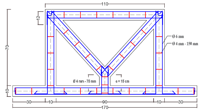
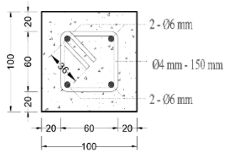
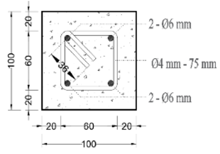
Table 1: Cyclic loading phase of the frame
| Phase | Load (kg) | Push-Pull Cycle (times) |
|---|---|---|
| 1 | 25% Ultimate P = 1313 | 5 |
| 2 | 50% Ultimate P = 2625 | 5 |
| 3 | 75% Ultimate P = 3927,5 | 5 |
| 4 | 100% Ultimate P = 5250 | 5 |
This research focuses on the role of GGBFS on the seismic behavior of reinforced concrete eccentrically braced frames (EBF) with vertical link beams and tightly spaced transverse reinforcement (75 mm). Specifically, the aspects investigated include crack pattern, crack distribution, and collapse mechanism. Also, ductility, lateral capacity, and deformation with comparison with last research.
Moreover, vibrators are also used to minimize voids and ensure even concrete distribution34). After, a curing process is carried out by covering the test object with burlap sacks, then sprinkling it with water. This method maintains water stability and moisture to achieve maximum concrete hydration35). The tests consisted of compressive strength tests on cylindrical specimens and cyclic loading at 56 days of concrete age. Cyclic loading works horizontally centered through the load cell and then given to the upper joint on both sides.
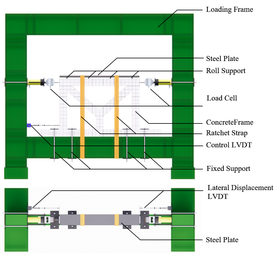
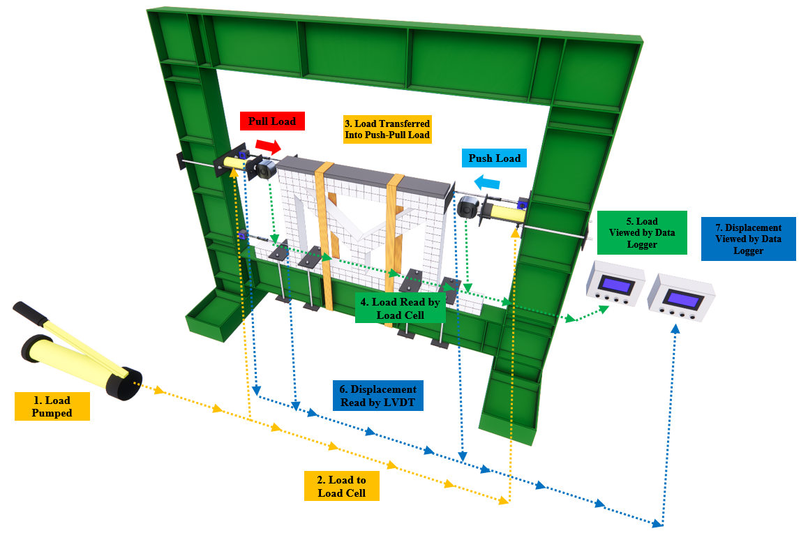
According to previous research, the loading uses the concept of load control with a maximum value of 5250 kg16). This value is divided into 4 phases covering five cycles, where one cycle is the push and pull load on the frame. 4 phases are used to determine the behavior of the frame at progressively higher loads, and 5 repetitive cycles are used to determine durability at the same load. A stable cyclic load will accurately describe the behavior of the specimen. Specifically, low to maximum loads on the specimen will result in deformation that is easier to observe36). Detailed cyclic loading phases and cycles are shown in Table 1. Note that the load cell is positioned parallel to the LVDT, which is useful for measuring horizontal displacement. This is the reason why the vertical displacement is limited by means of iron and reinforcement, which is then secured by iron and ratchet strap, as shown in Figure 3. Finally, two sample results were obtained, namely the maximum stress of the cylindrical specimens and the frame, which included the maximum load, number of cracks, crack pattern, and collapse mechanism in the initial, yield and ultimate phases. These data were then analyzed to determine the role of the vertical link beam and GGBFS on the frame.
3. Result and Discussion
Compressive strength tests were performed to determine the actual strength and uniformity of the concrete. Five specimens of each frame specimen were used at 56 days. The findings indicated that the mean compressive strength for CBF was 27.84, while EBF-V-15 and EBF-V-25 specimens registered strengths of 28.23 and 29.06. In other words, it shows that the specimens of each specimen achieved the design compressive strength and the values that were close to each other. This phenomenon can be attributed to a multitude of factors, including the efficacy of the casting and curing processes. Furthermore, the study also mentioned that the wet rug curing method had the highest strength compared to other methods such as simply soaking in water. Employing the appropriate method ensures the attainment of high and uniform compressive strength values. This phenomenon is evident in the uniform compressive strength values and the achieved plan compressive strength35).
3.1. Load – Displacement Curve
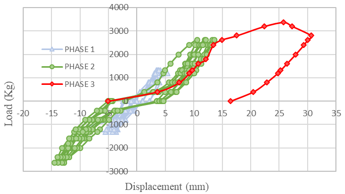
Through testing, 6 cyclic frame test results were obtained that included 2 specimens each of CBF, EBF-V-15, and EBF-V-25. It was thus determined that the hysteresis curves were obtained for a range of positive and negative shear and tensile loads. The results of the hysteresis curve can then be observed in Figure 4 until Figure 6, where the dominant structure is only able to reach half a cycle at the shear load during the peak phase. Each image is selected as the best representative of the CBF, EBF-V-15, and EBF-V-25 samples.
By visual observation, CBF has been demonstrated to exhibit the highest capacity in comparison to other specimens with a sloping and wide curve with a visible range of yield and end points, respectively. In addition, this curve is also very accurate in describing the experimental test of CBF. Specifically, the high load and concentric diagonal bracing elements resulted in a less ductile collapse with a limited ductility ratio.
A comparative study was also conducted where the lateral strength of CBF with GGBFS combination tends to decrease by 3 - 35% compared to OPC specimens. However, GGBS has the advantage of improving the mechanical properties after 56 days.
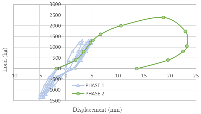
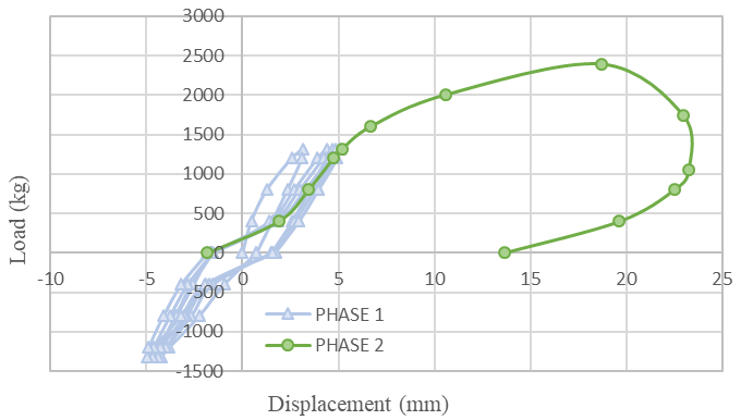
In addition, it is evident that GGBFS has a substantial impact on enhancing ductility, as demonstrated by its displacement value, which exhibits a 29.68% increase in comparison with OPC. Furthermore, each EBF specimen experienced a decrease in lateral capacity compared to the OPC specimens. Successively, EBF with vertical links of 15 and 25 cm obtained smaller values of 7% and 23.9%. In contrast, the displacement values actually increased by 55.5% and 27% for EBF 15 and 25 cm17,18).
Visually, specimen EBF-V-25 has a smaller curve area than EBF-V-15 as shown in Figure 5 and Figure 6. This is due to the longer link beam, which reduces the load and displacement capacity. The present result differs somewhat from earlier research findings on ductility, which demonstrated an increase in ductility with an increase in the length of the vertical link37). This can be explained by the dense reinforcement (75 mm) in the link beam. It gives a higher restraining effect to the longer link beam (EBF-V-25), thus limiting the frame deformation, which is directly related to the limited ductility. But overall, the vertical link beam plays a very good role in providing a stable post ultimate behavior characterized by a sloping curve. This highlights the important role of the vertical link beam in ensuring the stability of the structure by connecting the frames in the EBF38).
3.2. Ductility of Frames
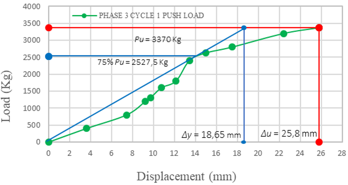
The yield point of the test is difficult to identify because it is affected by numerous factors. Therefore, the yield condition, including load and displacement, can be estimated using the secant stiffness method39). The yield displacement is determined based on the yield load, which is taken as 75% of the ultimate load, as illustrated in Figure 8.
Higher eccentricity in the vertical link beam can enhance ductility by directing horizontal lateral loads toward a shear-dominated failure mechanism18). This is reflected in the average ductility value of 1.515 for the EBF-V-15 specimen, which is higher than that of the CBF specimen with a value of 1.197. However, several findings do not fully align with this theoretical expectation. The EBF-V-25 specimen, for example, exhibits a lower average ductility of 1.421. This condition is attributed to the denser transverse reinforcement in the link beam (75 mm) compared with the other frame members (150 mm). The tighter reinforcement provides greater confinement, which restricts deformation in the EBF-V-25 specimen. Consequently, reduced deformation leads to a decrease in the overall ductility value.
In addition, the presence of GGBFS plays a significant role in improving frame ductility. A notable increase in ultimate displacement was observed, where the CBF specimen containing GGBFS reached an average value of 23.565 mm, which is 57.14% higher than that of the OPC specimen. This indicates that GGBFS contributes to enhancing the structural collapse mechanism, making it more ductile, as shown by the increase in ductility from 1.140 to 1.19717). These findings suggest that using GGBFS as a partial replacement for OPC results in a structure with more ductile collapse behavior32). Overall, the results indicate that the EBF-V-15 specimen demonstrates the most favorable performance, exhibiting ideal strength along with the highest ductility compared with the other specimens, particularly CBF. Finally, ductility can be determined from the ratio between ultimate displacement (Δu) and yield displacement (Δy) during the maximum phase and loading cycle of the frame, as presented in Table 2.
Table 2: Ductility of concrete bracing frames
| Code | Eccentricity | Yield Load (Py) | Ultimate Load (Pu) | Δu | Δy | Ductility Ratio (Δy /Δy) | Average Ductility Ratio |
|---|---|---|---|---|---|---|---|
| (cm) | (Kg) | (Kg) | (mm) | (mm) | (Kg/mm) | (Kg/mm) | |
| A.1 | 0 | 1968.75 | 2625 | 21.33 | 21.10 | 1.011 | 1.197 |
| A.2 | 0 | 2527.50 | 3370 | 25.80 | 18.65 | 1.383 | |
| B.1 | 15 | 1829.25 | 2439 | 18.01 | 13.76 | 1.309 | 1.515 |
| B.2 | 15 | 1792.50 | 2390 | 18.68 | 10.85 | 1.722 | |
| C.1 | 25 | 1303.50 | 1738 | 8.88 | 6.67 | 1.331 | 1.421 |
| C.2 | 25 | 1497.75 | 1997 | 17.12 | 11.33 | 1.511 |
Table 3: Stiffness of concrete bracing frames
| Code | Eccentricity | Ultimate Tensile Push (PuP) | Ultimate Pull Load (PuT) | ΔuP Push | ΔuT Pull | K (ΣPu/ΣΔu) | Average Stiffness |
|---|---|---|---|---|---|---|---|
| (cm) | (Kg) | (Kg) | (mm) | (mm) | (Kg/mm) | (Kg/mm) | |
| A.1 | 0 | 2625 | 2625 | 21,33 | 20,14 | 126,60 | 137,734 |
| A.2 | 0 | 3370 | 2625 | 25,80 | 14,47 | 148,87 | |
| B.1 | 15 | 2439 | 1313 | 18,01 | 4,29 | 168,25 | 162,380 |
| B.2 | 15 | 2390 | 1313 | 18,68 | 4,98 | 156,5 | |
| C.1 | 25 | 1738 | 800 | 8,88 | 20,95 | 85,08 | 109,437 |
| C.2 | 25 | 1997 | 1313 | 17,12 | 7,62 | 133,79 |
3.3. Stiffness of Frames
Frame stiffness is another important aspect that needs to be considered in structural performance. The stiffness of the frame is strongly influenced by the eccentricity length, which is represented by the vertical link beam. In general, increasing the eccentricity results in a decrease in the overall stiffness of the frame.
Based on the test results, specimen B (EBF-V-15) shows a higher stiffness value compared to specimen A (CBF). This increase is attributed to the tighter spacing of transverse reinforcement (75 mm) in the link beam. However, this behavior is not observed in the EBF-V-25 specimen. Instead, EBF-V-25 experiences a significant stiffness reduction of 32.60% compared with EBF-V-15, as presented in Table 3.
These results indicate that a transverse reinforcement spacing of 75 mm may have a negative effect on bracing systems with larger eccentricities19). When the link beam becomes longer, the failure mechanism tends to shift from shear-dominated behavior to flexural behavior. Therefore, very tight transverse reinforcement spacing in longer link beams is not recommended because it does not effectively improve stiffness and may adversely affect structural performance.
3.4. Initial Condition Cracks
Crack pattern analysis is useful to determine the seismic behavior indicated by the frame's crack pattern and collapse pattern. Observations were made on the frames from initial yield to ultimate conditions, focusing on the number, location, and classification of cracks. In general, the crack's direction determines the crack's classification as either flexural or shear. Cracks will form as the concrete begins to reach and exceed its ultimate strength and will spread throughout the cross section uniformly with different characteristics40).
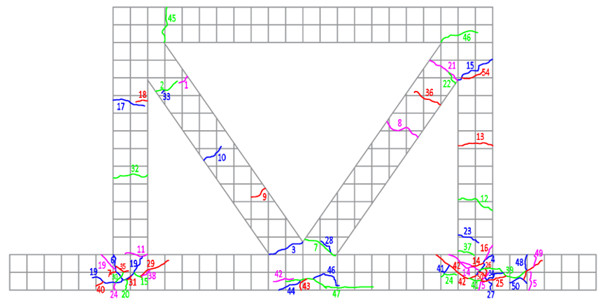
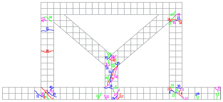
The CBF specimens had the highest number of cracks among the other specimens in the cyclic loading test. The first crack occurred in phase 1 of cycle one under shear load conditions in the 800 - 1313 kg range at the diagonal bracing marked with notations 1 – 3. This confirms that the first melt occurred at the diagonal strut. This diagonal structure will provide support and reduce tension on other elements. Without it, the structure would only be able to support the cyclic load through the depicted cracks in the frame and columns41). Another crack appeared at the lower right joint with notations 5-7.
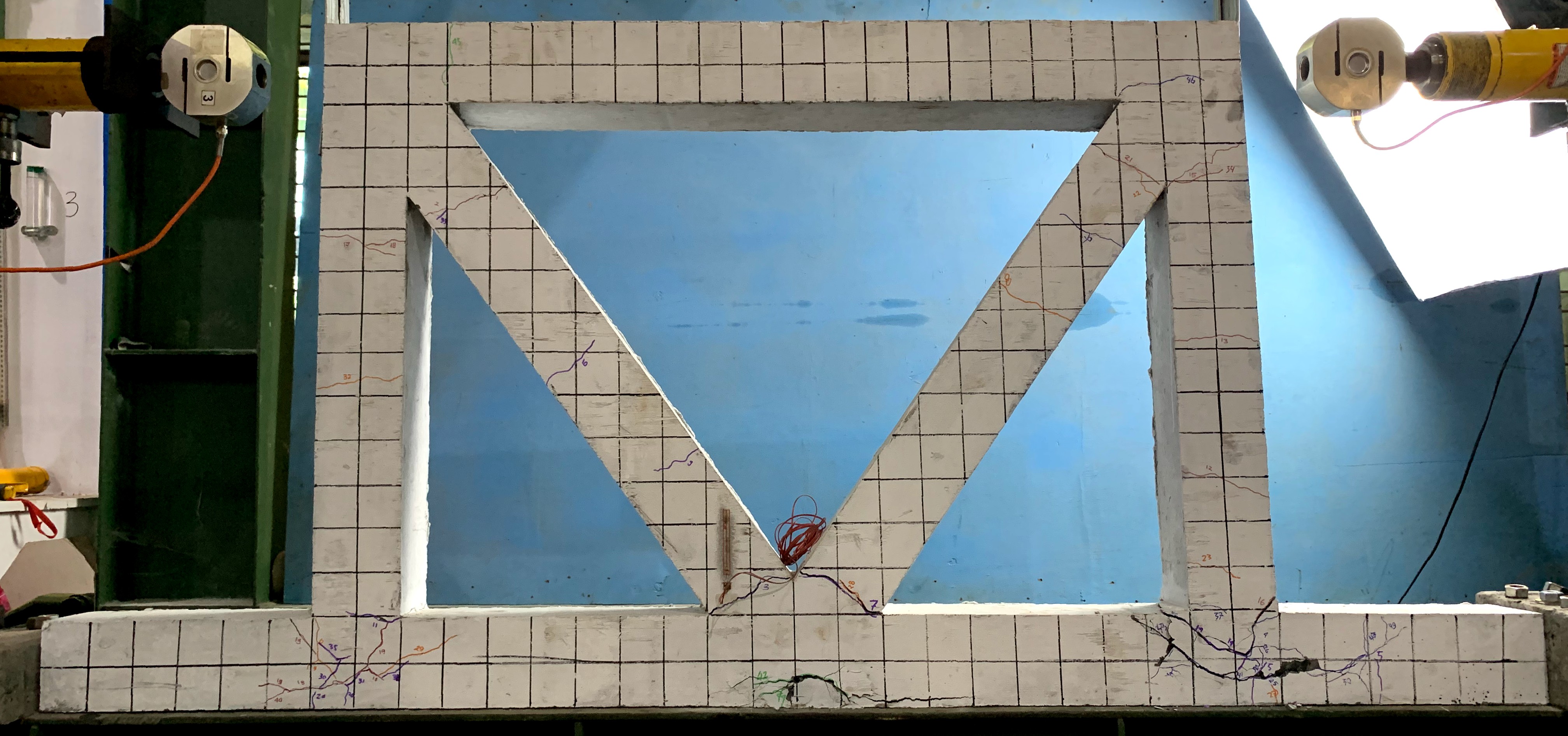
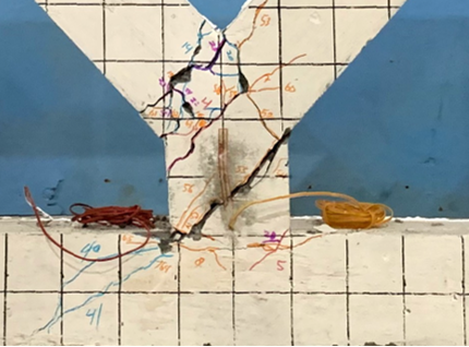
This crack can actually be seen in Figure 7. These cracks are classified as flexural because they have a pattern perpendicular to the member.
EBFs have lower stiffness but nonlinear behavior focused on the vertical link beam element17). Link beams also play a role in improving the ductile behavior with damage concentrated on this element19).
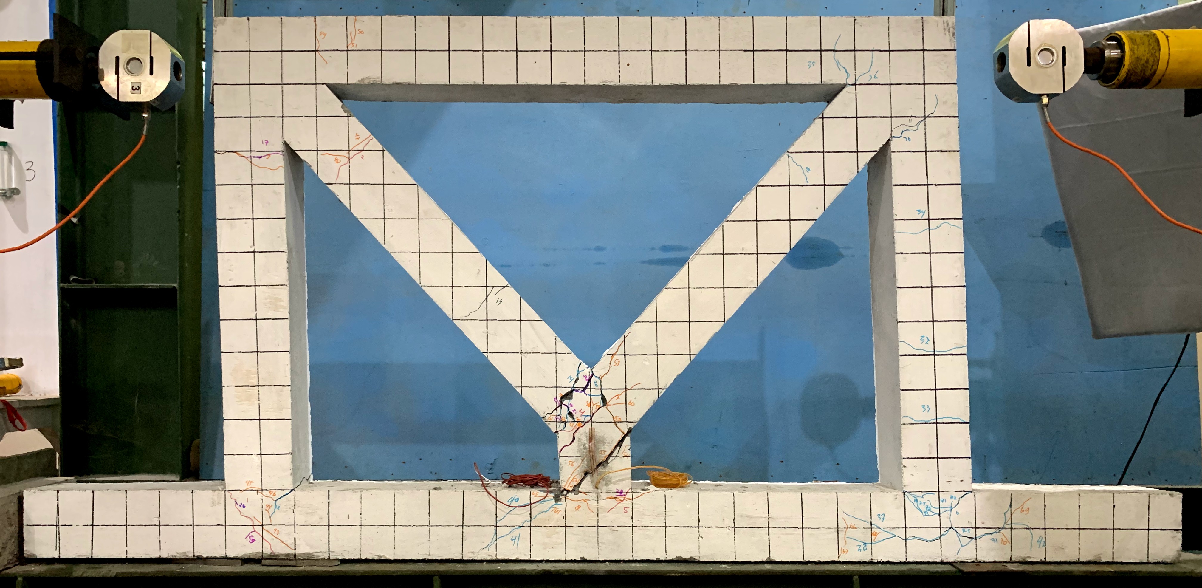
The cyclic test results show that the initial crack in the EBF-V-15 specimen occurred in the first load cycle of shear, labeled 1-8. Visually, the cracks in the first cycle were evenly distributed on the right-left side joint and the link beam, which occurred in the load range of 800-1313 kg. Furthermore, the cracks can be classified as shear cracks since they are diagonal to the element.
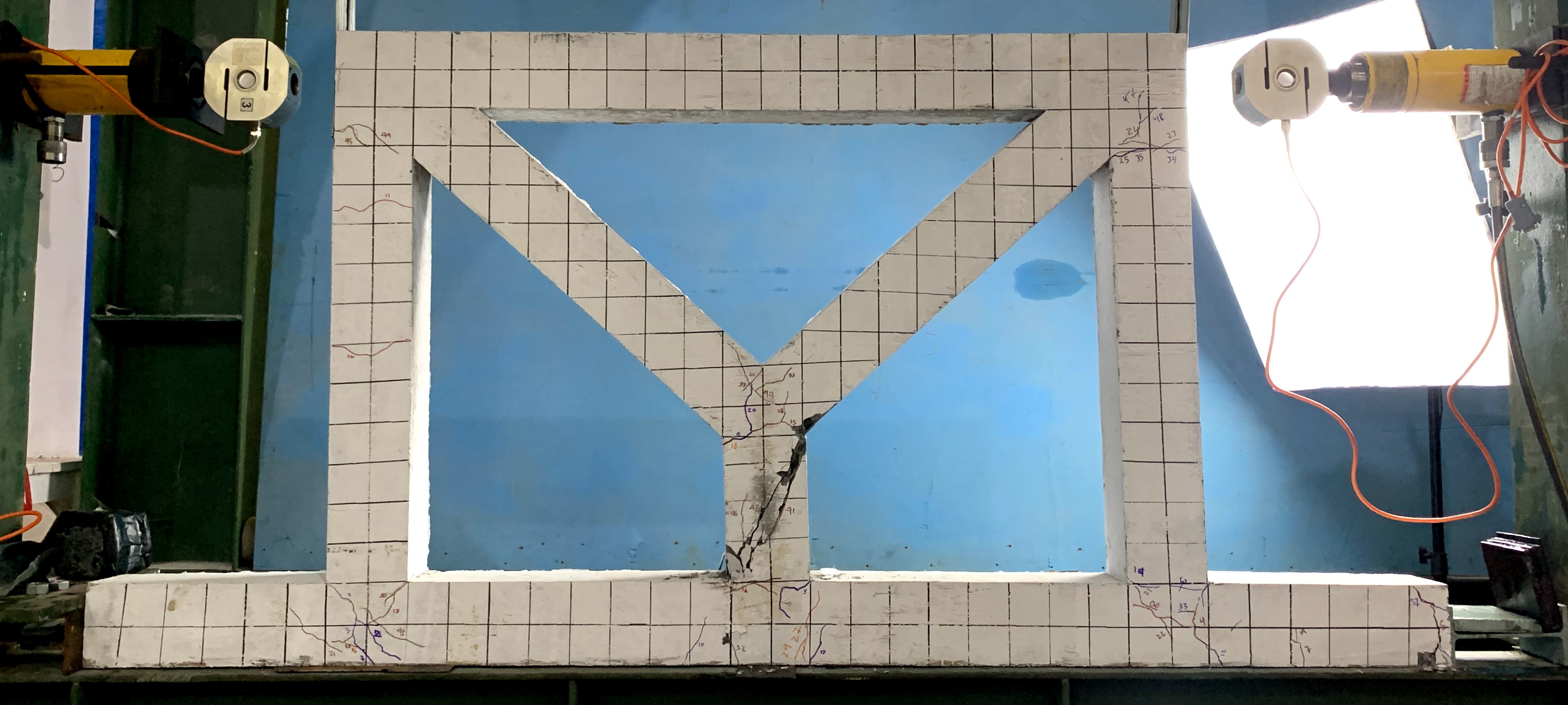
The cyclic test results also show that the EBF-V-25 specimen has a cracking pattern in the first loading phase and cycle. During the frame loading, cracking occurred in the 800 - 1313 kg load range. The cracking started at the lower joint on the right side with notation 1, then continued on the left side with notations 2 and 3. The cracks at the right and left side joints occurred because the column member was subjected to tensile and compressive bending. The beam also cracked at notations 6 and 9. Moreover, the cracks at the joints are classified as shear cracks with diagonal shapes due to the large shear stress in this region. On the other hand, the vertical beam started to develop flexural cracks with a pattern perpendicular to the element. Visually, the initial condition showed that the crack patterns in these critical sections were evenly distributed and symmetrical.
3.5. Yield Condition Cracks
Due to the nonlinear nature of the specimen under load, it will be difficult to determine the yield criterion. Therefore, the secant stiffness method is used to simplify the determination of the yield strength of the frame (Park, 1989). The CBF specimen achieved a load (Py) and displacement (Δy) of 2527,5 kg and 18.65 mm as shown in Figure 8. There was a significant increase in cracks, with 43 evenly distributed at the joints, columns, and bracing.
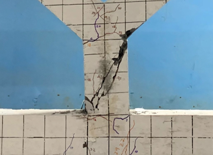
The EBF-V-15 yield condition by secant stiffness analysis obtained a load (Py) of 1829 kg and a deformation (Δy) of 13.76 mm. According to the theory, the yielding occurred in the vertical beam indicated by the notation 29-34 and be-longs to the diagonal shear crack as can be seen in Figure 9. Therefore, the shear crack means that the vertical link beam in specimen EBF-V-15 belongs to the short link classification9).
Through the same analysis, the EBF-V-25 specimen achieved a yield load (Py) of 1497.75 kg with a displacement (Δy) of 11.30 mm. There is an increase in the number of cracks, with a total of 41 cracks in the yield state where the longer beam plays a very good role in crack localization, with the largest number of 11 cracks dominated by shear cracks with a few flexural cracks with diagonal and perpendicular to the beam, respectively, as shown in Figure 9. This system can be likened to a spring, where all tension from cyclic loads will be directed to the link beam during yield conditions36). Therefore, the 25 cm vertical beam is the intermediate beam because it combines shear and flexural cracks9). In the other hand, shear stress has been identified as a primary factor in the process of shear collapse. Shear stress exceeding the shear stress capacity causes cracking as evidenced by the presence of substantial diagonal crack pattern in the vertical link beam18,37).
3.6. Ultimate Condition Cracks
Finally, the CBF specimen had the highest load capacity as it reached phase 3 cycle one load (Pu) of 3370 kg with a displacement (Δu) of 25.8 m but with an increase in the number of cracks to only 50. The test was stopped when failure occurred at notation 3, characterized by a wider crack, according to Figure 10. The CBF showed a crack distribution concentrated in both sides of diagonal bracing and bottom joint. In addition, the cracks were dominated by flexural cracks in the bracing and oblique shear cracks in the joints, which were predominated by small cracks. Moreover, the fissures manifest visual symmetry on both sides. There was an augmentation of 20 cracks in comparison with the specimen devoid of GGBFS19). More finer cracks accurately describe a more ductile frame behavior32). Therefore, it can be concluded that GGBFS can improve the collapse behavior to be more ductile.
Moreover, EBF-V-15 has been observed to exhibit a reduced ultimate load in relation to CBF. This phenomenon can be attributed to the influence of the vertical link beam, which prioritises the enhancement of ductility due to its non-rigid nature17). This is characterized by the fact that EBF-V-15 can only achieve an ultimate load (Pu) of 2439 kg with a displacement (Δu) of 18.01 mm. Overall, the nonlinear behavior is dominant in the vertical link, as evidenced by the larger number of cracks, which minimizes damage to the frame. It is also beneficial to keep the frame in an elastic state as much as possible. Finally, the test was terminated when the frame reached its maximum capacity with the wider cracks indicated by notation 17 in Figure 10. In conclusion, EBF-V-15 has a more ductile behavior compared to CBF. This is characterized by almost the same number of cracks but at a lower loading phase.
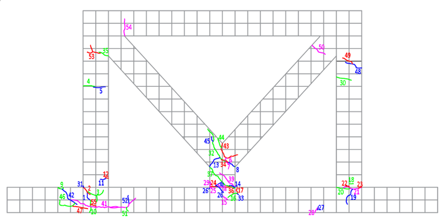
EBF-V-25 compared to EBF-V-15 specimens experienced a decrease in load-carrying capacity. The EBF-V-25 specimen could only reach the ultimate state with a load (Pu) of 1997 kg and a displacement (Δu) of 17.12 mm in the loading phase of 2 cycles 1. Specifically, this is due to the longer beam, which results in a lower stiffness value. Furthermore, the role of tighter transverse reinforcement (75 mm) also greatly helps in maintaining the structure's high seismic capacity. The best results were obtained from specimen EBF-V-15. Although the value is lower than in previous studies, from 2625 kg to 2439 kg or around 7%, the structure is still able to maintain its lateral capacity at higher deformations. This is indicated by an increase in deformation of 18.68 mm, from only 8.30 mm previously18).
There were 10 additional cracks from the yield state for 51 cracks. This value is also higher than EBF-V-15, which can only have 36 cracks. The higher number of cracks indicates that the longer beam works very well in providing a more ductile collapse behavior even at low loading phases.
Table 4: Phase-cylce to crack
| Specimen | Phase – Cycle | Load (kg) | Number of Cracks |
|---|---|---|---|
| CBF | 1 – 1 | 1313 | 7 |
| 1 – 2 | 1313 | 8 | |
| 1 – 3 | 1313 | 8 | |
| 1 – 4 | 1313 | 8 | |
| 1 – 5 | 1313 | 8 | |
| 2 – 1 | 2625 | 23 | |
| 2 – 2 | 2625 | 32 | |
| 2 – 3 | 2625 | 38 | |
| 2 – 4 | 2625 | 40 | |
| 2 – 5 | 2625 | 43 | |
| 3 – 1 | 3370 | 50 | |
| EBF-V-15 | 1 – 1 | 1313 | 8 |
| 1 – 2 | 1313 | 13 | |
| 1 – 3 | 1313 | 15 | |
| 1 – 4 | 1313 | 15 | |
| 1 – 5 | 1313 | 15 | |
| 2 – 1 | 2439 | 36 | |
| EBF-V-25 | 1 – 1 | 1313 | 9 |
| 1 – 2 | 1313 | 31 | |
| 1 – 3 | 1313 | 34 | |
| 1 – 4 | 1313 | 37 | |
| 1 – 5 | 1313 | 39 | |
| 2 – 1 | 1997 | 51 |
3.7. Phase – Cycle Loading to Crack
Overall, CBFs had a higher number of cracks compared to EBFs. However, the cracks occurred at higher load stages with more cycles, so this number can only be attributed to the greater capacity of the CBF. The CBF was able to reach the highest load of 3370 kg, which directly correlates to a large number of cracks (50 cracks). On the other hand, the EBF was able to achieve approximately the same number of cracks with a lower loading phase, as shown in Table 4. Moreover, when plotted in the graphs, a ductile behavior of the EBF is obtained, where there is a uniform increase of cracks with respect to the load and load cycles in Figure 11 and Figure 12. These results also show that the use of a 15 cm vertical beam (EB-V-15) improves the collapse with a large number of cracks that are concentrated and symmetrical, but with a high capacity. This indicates that there is an improvement in ductile behavior with the use of link beams17). Conversely, the capacity of the vertical link beam can be augmented by the implementation of steel stiffener plates, which offer additional benefits as a structural repair mechanism41).
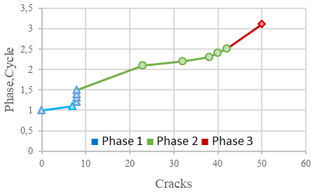
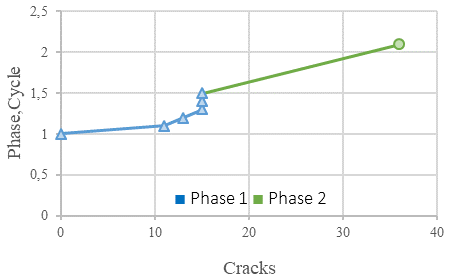
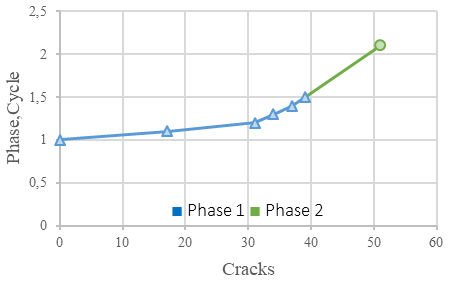
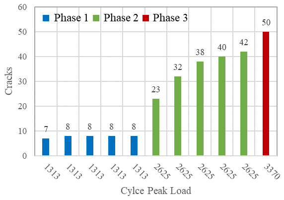
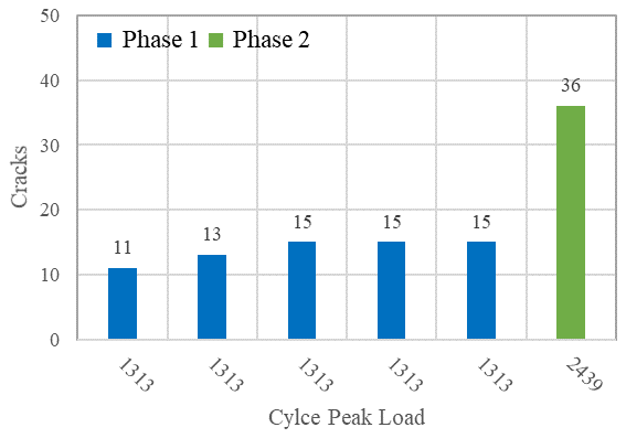
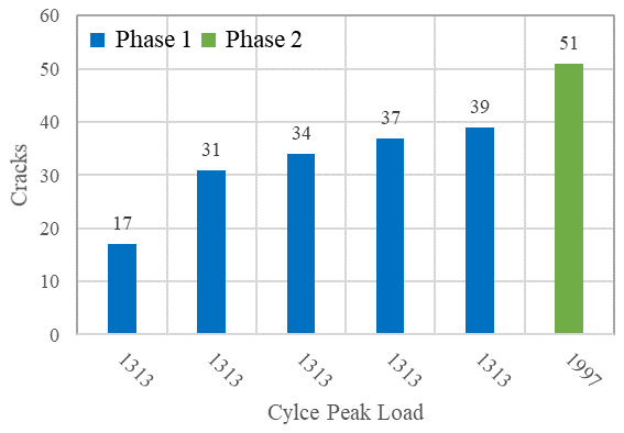
Table 5: Load – displacement to crack of yield and ultimate
| Code | Phase – Cycle | Load (kg) | Displacement (mm) | Cracks |
|---|---|---|---|---|
| CBF | 2-5 | 2527,5 | 18.65 | 43 |
| 3-1 | 3370 | 25.80 | 50 | |
| EBF-V-15 | 2-1 | 1829 | 13.76 | 34 |
| 2-1 | 2439 | 18.68 | 36 | |
| EBF-V-15 | 2-1 | 1497.75 | 11.30 | 41 |
| 2-1 | 1997 | 17.12 | 51 |
3.8. Load – Displacement to Crack
High loads are closely related to the resulting deformation values. Tests show that as the load increases, there is a positive correlation with increasing dis-placement as shown in Table 5. In other words, a greater displacement corresponds to an increased number of cracks evenly distributed in each framed specimen. Therefore, this parameter also indicates that GGBFS plays a very good role in improving the ductility of the structure by increasing the number of uniformly distributed cracks with each increase in load and displacement. More importantly, GGBFS with smaller particles can play an active role in improving the ductile collapse behavior by reducing the number of voids in the concrete so that fine cracks are uniformly distributed in all parts of the frame. Furthermore, GGBFS has been shown to have a significant impact on the distribution of symmetrical cracks, with a uniform effect on both sides of the bracing system32).
4. Conclusion
In conclusion, it is evident that the CBF possesses the greatest capacity, although it is limited ductile behavior based on both hysteresis curves and cracking behavior. Therefore, EBF-V-15 has the advantage of the best seismic performance with high capacity and ductile collapse behavior. EBF-V-15 can withstand a load of 2439 kg at a high deformation of 18.68 mm. 7% smaller capacity but with a 23.9% increase in displacement. In addition, the combination with dense transverse reinforcement (75 mm) is able to increase the ductility and stiffness with high and stable nonlinear displacement compared to OPC. The contribution of the link beam provide a stable nonlinear behavior characterized by an inclined curve, while keeping the main structure elastic. In addition, longer link beams result in a combination of shear and flexural collapse patterns. More importantly, GGBFS greatly improves ductile behavior by contributing to many smooth, symmetrical cracks throughout the frame specimen.
References
- Z.Q. Hassan, and S. Al-Wazni, “A review of retrofitting in the structural steel buildings using bracing systems,” IOP Conf. Ser. Earth Environ. Sci., 1232 (1) (2023). doi:10.1088/1755-1315/1232/1/012031.
- M.A. Kafi, A. Kheyroddin, and R. Omrani, “New steel divergent braced frame systems for strengthening of reinforced concrete frames,” Int. J. Eng. Trans. A Basics, 33 (10) 1886–1896 (2020). doi:10.5829/IJE.2020.33.10A.07.
- B.H. Ali, E.M. Güneyisi, and M. Bigonah, “Assessment of different retrofitting methods on structural performance of rc buildings against progressive collapse,” Appl. Sci., 12 (3) (2022). doi:10.3390/app12031045.
- F. Barbagallo, M. Bosco, E.M. Marino, and P.P. Rossi, “Seismic performance and cost comparative analysis of steel braced frames designed in the framework of ec8,” Eng. Struct., 240 (November 2020) 112379 (2021). doi:10.1016/j.engstruct.2021.112379.
- O. Moammer, H.M. Madani, K.M. Dolatshahi, and M. Ghyabi, “Collapse risk and earthquake-induced loss assessment of buildings with eccentrically braced frames,” J. Constr. Steel Res., 168 105998 (2020). doi:10.1016/j.jcsr.2020.105998.
- R. Chacón, A. Vega, and E. Mirambell, “Numerical study on stainless steel i-shaped links on eccentrically braced frames,” J. Constr. Steel Res., 159 67–80 (2019). doi:10.1016/j.jcsr.2019.04.014.
- C. Ramonell, and R. Chacón, “On the topological optimization of horizontal links in eccentrically braced frames,” J. Constr. Steel Res., 185 (July) (2021). doi:10.1016/j.jcsr.2021.106887.
- P. Prasad, and B. Prasad, “Performance behavior of eccentrically braced steel frame under seismic loading,” Int J Innov Technol Explor Eng, 8 1077–1090 (2019).
- G. Ince, “Effect of link length in retrofitted rc frames with y eccentrically braced frame,” (September) (2023). doi:10.12989/scs.2022.43.5.553.
- M.G. Vetr, and A. Ghamari, “Experimentally and analytically study on eccentrically braced frame with vertical shear links,” Struct. Des. Tall Spec. Build., 28 (5) e1587 (2019).
- A. Ghobarah, and H.A. Elfath, “Rehabilitation of a reinforced concrete frame using eccentric steel bracing,” 23 745–755 (2001).
- C. Fang, W. Wang, C. Qiu, S. Hu, G.A. MacRae, and M.R. Eatherton, “Seismic resilient steel structures: a review of research, practice, challenges and opportunities,” J. Constr. Steel Res., 191 (January) 107172 (2022). doi:10.1016/j.jcsr.2022.107172.
- H.S. Grover, S. Deswal, and A. Adhikari, “Analysis and estimation of atmospheric corrosivity of zinc protective coating on steel substrate,” Evergreen, 11 (03) 1753–1762 (2024). doi:10.5109/7281922.
- X.-Y. Cao, G. Wu, D.-C. Feng, and X.-J. Zu, “Experimental and numerical study of outside strengthening with precast bolt-connected steel plate–reinforced concrete frame-brace,” J. Perform. Constr. Facil., 33 (6) (2019). doi:10.1061/(asce)cf.1943-5509.0001351.
- D. Setyowulan, L. Susanti, and M.N. Wijaya, “Study on the behavior of a one way eccentric braced frame under lateral load,” Asian J. Civ. Eng., 21 (4) 733–739 (2020). doi:10.1007/s42107-020-00234-2.
- L. Susanti, and M. Wijaya, “Eccentricity effect on the cyclic response of braced frame type-v,” Civ. Environ. Sci., 005 (01) 089–095 (2022). doi:10.21776/ub.civense.2022.00501.9.
- S. Syafirra, M.N. Wijaya, and L. Susanti, “Behavior of eccentrically braced frames on portal structure under cyclic load,” AIP Conf. Proc., 2688 (April 2022) (2023). doi:10.1063/5.0111512.
- L. Susanti, and U. Brawijaya, “CYCLIC behavior and critical part of eccentric,” 537–546 (2024).
- M.N. Wijaya, L. Susanti, and S. Syafirra, “Effect of shear stirrup space on short link beam of eccentric braced frame (ebf) v-type under cyclic loading,” AIP Conf. Proc., 2447 (Gcee) 1–8 (2021). doi:10.1063/5.0072627.
- P. Ganesh, and A.R. Murthy, “Tensile behaviour and durability aspects of sustainable ultra-high performance concrete incorporated with ggbs as cementitious material,” Constr. Build. Mater., 197 667–680 (2019). doi:10.1016/j.conbuildmat.2018.11.240.
- S. Kumari, S. Jaglan, A. Chouksey, R. Walia, A. Ahlawat, A. Garg, and M. Verma, “Carbon footprint analysis of cement production in india,” Evergreen, 11 (4) 2881–2889 (2024). doi:10.5109/7326930.
- S. Singh, S.K. Singh, R. Kumar, A. Shrama, and S. Kanga, “Finding alternative to river sand in building construction,” Evergreen, 9 (4) 973–992 (2022). doi:10.5109/6625713.
- A. Przybek, K. Setlak, J. Piątkowski, K. Rzepka, P. Romańska, J. Mikuła, and M. Łach, “Alkaline-activated materials for co 2 capture – literature review , own observations , and future perspectives,” Evergreen, 12 (03) 1664–1679 (2025). doi:10.5109/7388857.
- R. Karolina, J. Tarigan, H. Hardjasaputra, and R.A.D. Silalahi, “Analysis of geopolymer mortar compressive strength based on fly ash and ggbfs as patch repair material,” IOP Conf. Ser. Earth Environ. Sci., 1195 (1) (2023). doi:10.1088/1755-1315/1195/1/012032.
- M. Shariq, J. Prasad, and A.K. Ahuja, “Strength development of cement mortar and concrete incorporating ggbfs,” (2008).
- J. Ahmad, K.J. Kontoleon, A. Majdi, M.T. Naqash, A.F. Deifalla, N. Ben Kahla, H.F. Isleem, and S.M.A. Qaidi, “A comprehensive review on the ground granulated blast furnace slag (ggbs) in concrete production,” Sustain., 14 (14) (2022). doi:10.3390/su14148783.
- F. Hussain, I. Kaur, and A. Hussain, “Reviewing the influence of ggbfs on concrete properties,” Mater. Today Proc., 32 997–1004 (2020). doi:10.1016/j.matpr.2020.07.410.
- N. Bheel, S.A. Abbasi, P. Awoyera, O.B. Olalusi, S. Sohu, C. Rondon, and A.M. Echeverriá, “Fresh and hardened properties of concrete incorporating binary blend of metakaolin and ground granulated blast furnace slag as supplementary cementitious material,” Adv. Civ. Eng., 2020 1–8 (2020). doi:10.1155/2020/8851030.
- G. Zhakypova, S. Uderbayev, N. Saktaganova, G. Abyieva, A. Budikova, and A. Zhapakhova, “Properties of fine-grained concrete using ash of kazakhstan,” Evergreen, 10 (2) 830–841 (2023). doi:10.5109/6792835.
- A.M. Said, M.S. Islam, M.S. Zeidan, and M. Mahgoub, “Effect of nano-silica on the properties of concrete and its interaction with slag,” Transp. Res. Rec., 2675 (9) 47–55 (2021). doi:10.1177/0361198120943196.
- L. Wang, M.L. Chen, and D.C.W. Tsang, “Green remediation by using low-carbon cement-based stabilization/solidification approaches,” Elsevier Inc., 2019. doi:10.1016/B978-0-12-817982-6.00005-7.
- C.L. Oh, S.W. Lee, N.A. Yahya, G. Pandulu, and M.R.M. Zain, “Tensile behaviour of slag-based engineered cementitious composite,” Pertanika J. Sci. Technol., 30 (1) 303–317 (2022). doi:10.47836/pjst.30.1.17.
- T. Tuswan, R. Muhammad, A.R. Prabowo, I. Yaningsih, W. Wibowo, T. Muttaqie, and I. Istanto, “Assessment of seismic responses on the concrete gravity dam subjected to the geometrical design parameters using finite element approach,” Evergreen, 11 (3) 2217–2233 (2024). doi:10.5109/7236865.
- R. Kumar, M. Verma, and N. Dev, “Analysis of pce-based superplasticiser for the different types of cement using marsh cone test,” Evergreen, 11 (02) 665–672 (2024). doi:10.5109/7183337.
- S. Ram, A. Dengri, and R. Kumar, “Assessment of compressive strength in ordinary portland cement concrete: a study of curing methods and duration,” Evergreen, 11 (2) 640–651 (2024). doi:10.5109/7183321.
- E.D. Purnomo, E.D. Purnomo, M. Azka, L. Hotma, and A. Aziz, “The prediction of stress and safety factor of shock absorber based on cyclic loading using finite element method the prediction of stress and safety factor of shock absorber based on cyclic loading using finite element method,” Evergreen, 10 (4) 2456–2463 (2023).
- P. Ranima, L. Susanti, and M.N. Wijaya, “Ductility of y-type eccentric braced frame (ebf) under cyclic loading,” AIP Conf. Proc., 3043 (1) (2024). doi:10.1063/5.0206595.
- F. Abdelhamid, D. Yahiaoui, M. Saadi, and N. Lahbari, “Lateral reliability assessment of eccentrically braced frames including horizontal and vertical links under seismic loading,” Eng. Technol. Appl. Sci. Res., 12 (2) 8278–8283 (2022). doi:10.48084/etasr.4749.
- R. Park, “Structural assemblages from laboratory testing,” Bull. New Zeal. Natl. Soc. Earthq. Eng., 22 (3) 155–166 (1989).
- N. Handika, B.O.B. Sentosa, S. Astutiningsih, A.G. Manohara, C.S. Putri, and D. Rahmadhanti, “Mechanical properties and fracture patterns in oil palm shell concrete with various cement types using digital image correlation,” Evergreen, 11 (2) 1375–1382 (2024). doi:10.5109/7183449.
- Y. Helal, R. Garcia, T. Imjai, P. Aosai, M. Guadagnini, and K. Pilakoutas, “Seismic behaviour of exterior rc beam-column joints repaired and strengthened using post-tensioned metal straps,” Bull. Earthq. Eng., 22 (6) 3261–3286 (2024). doi:10.1007/s10518-024-01904-1.